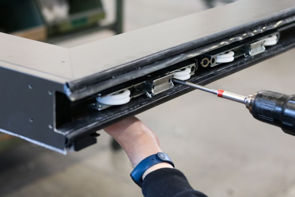
A linear motor converts electrical energy directly into straight-line motion without mechanical transmission, eliminating backlash and wear parts inherent to ballscrew or rack-and-pinion linear actuator drives. Catalog offerings from established motion vendors now span 71 product families in 7 families of linear motor stages, reflecting a mature direct-drive market [S2].
Selection pivots on five numbers first, everything else second: continuous force (N), peak force (N), stroke (mm), repeatability (µm), and thermal time constant or class. Buyers who fix those five values before opening a catalog avoid the most common failure mode — oversizing the motor and then discovering the linear guide rail cannot take the resulting moment load.
Force Profile: Continuous vs Peak vs RMS
Linear motor force data sheets always list three numbers, and confusing them is the single most common sourcing error in 2026. Continuous force is the thermal steady-state limit; peak force is the short-duration maximum (typically 2–3× continuous for under 1 second); RMS force is the time-averaged load that must remain below continuous rating [S3].
For a HIWIN LMSSA series ironcore module, model LMSSA20C200-1-100-K5.3A-S-B-A0000 specifies a 200 N continuous / 600 N peak envelope, mounted in a 200 mm-wide base [S3]. The 3:1 peak-to-continuous ratio is typical for ironcore designs; ironless coreless units generally peak at 1.5–2× continuous because they lack the iron flux path to absorb short-term current surges. Process engineers should compute the motion profile RMS first, then size continuous force at 1.25× RMS as a 25% design margin.
Stroke, Speed and the Ironless-vs-Ironcore Split
Ironless (coreless) linear motors dominate high-speed, high-acceleration applications because the moving coil has zero iron mass and zero cogging force. Catalog data shows HIWIN coreless XY platforms pairing 13S200 and 20S300 ironcore modules with E1/E2 drives to minimise velocity ripple [S3]. Ironcore motors deliver higher force density per unit coil mass, making them the default for long-stroke gantry and machine-tool retrofits.
Maximum speed is constrained by the linear encoder resolution, the drive bus cycle, and the resonant frequency of the mounting structure. The HIWIN SSA08 standard module is rated for 5 m/s maximum velocity with a 1,400 mm effective stroke and an 80 mm base width [S3]. Buyers targeting above 5 m/s should budget for a coreless architecture, optical scale feedback with sub-µm pitch, and a structural resonance check above 200 Hz.
Repeatability, Accuracy and the Direct-Drive Advantage

Direct-drive linear motors claim repeatability figures that no mechanical transmission can match, because there is no hysteresis, no backlash, and no screw lead error to compound. HIWIN SSA10 dustproof modules quote ±0.5 µm repeatability in the 100 N/200 N force tier, matched to application-specific precision needs [S3]. The complementary nano-grade Z-axis and nanoscale stage family targets sub-µm-class metrology with air-bearing (Daf) variants reserved for ultra-clean or ultra-smooth duty [S3].
Accuracy is a different number from repeatability, and the distinction matters in laser cutting, wire bonding, and semiconductor lithography. A coreless XY stage with ±0.5 µm repeatability may still show ±5 µm accuracy if the linear bearing straightness and the metrology reference are not compensated. Closed-loop 2D error compensation is built into the HIWIN E2 drive (GT variant) for exactly this reason [S3].
Thermal Management and Duty Cycle
Linear motors have a thermal time constant typically in the 30–90 second range for small form factors, rising to several minutes for large gantry forcers. Continuous force is the figure that defines the thermal ceiling, and it is usually measured with a 100 K winding temperature rise over a 25 °C ambient on a defined heatsink [S3]. A 200 V–240 V AC or 380 V–480 V AC supply feeds the E1 drive platform, which also accepts mega-ulink and EtherCAT for high-speed comms [S3].
For high-duty applications — pick-and-place, packaging lines running 24/7 — liquid cooling plates or forced-air housings are usually required to hold the winding below the insulation class. The E1 drive adds functional safety (STO) and a 3.2 kHz velocity loop bandwidth, which shortens tuning time and stabilises thermal drift during load transients [S3]. Buyers should treat thermal data as the binding spec, not continuous force, because tripping the thermal cut-out on a coreless coil is the most common field failure. For selection logic on adjacent motion topics, the Servo vs AC Motor for Gear-Backlash Loads breakdown is a useful cross-reference.
Selection Map: Which Architecture Fits Which Duty
Four architecture-and-application pairs cover the bulk of industrial 2026 buying decisions. First, ironless coreless stages for semiconductor inspection, laser scanning, and pick-and-place above 3 m/s — pair with 0.1 µm optical scales and a coreless-grade drive. Second, ironcore modules (SSA08 through SSA20) for general automation, FPD handling, and electronic assembly where 5 m/s and 1,400 mm strokes suffice and force density matters more than zero cogging [S3]. Third, air-bearing (Daf) linear motor platforms for metrology, optical inspection, and cleanroom semiconductor where straightness error below 0.5 µm/100 mm and ISO Class 3 environment are mandatory [S3]. Fourth, gantry dual-drive configurations for large-format machining, where the E1 drive's built-in gantry control algorithm synchronises the two forcers without external controller overhead [S3].
Engineers should NOT pick a mainstream ironcore module when: (a) the application demands sub-µm straightness over a stroke above 500 mm; (b) particulate contamination is present and a fully sealed module cannot be sourced; or (c) the load is ferromagnetic and the ironcore attraction force exceeds the bearing's preload budget. The shortlist logic is straightforward: fix continuous force, peak force, stroke, repeatability, and thermal duty; eliminate architectures that fail any one of those five; then compare the survivors on price, lead time, and service network. Buyers selecting motors for conveyor or transformer duties will find the VFD-Duty Motor Price & Cost Breakdown reference useful for sizing the upstream drive and brake hardware.
Integration Checklist Before Releasing the PO
Three integration points routinely get missed. Cable management: coreless coils have limited flex-cycle life, so a cable carrier with strain relief and a defined bend radius is mandatory for strokes above 300 mm. Feedback device: the linear encoder resolution should be at least 10× the required positioning accuracy, and the readhead must be shielded against the motor's magnetic fringing field. Service loop: HIWIN lists safety-rated drives (STO functional safety) and a 3.2 kHz velocity bandwidth, but field service is gated on the local distributor's spare-parts inventory rather than the catalog headline [S3].
Track the following signals over the next two quarters: (1) lead times for ironcore SSA20-class modules, currently the supply-constrained tier in the HIWIN lineup [S3]; (2) release of next-generation E2 GT drives with expanded 2D error compensation tables; (3) any vendor disclosure of nano-grade air-bearing standardised platforms that fold the Daf option into a single SKU. Buyers who lock the spec map today, in this order — force, stroke, repeatability, thermal, environment — will cut their selection cycle by roughly half and avoid the post-order rework that defines the bottom quartile of direct-drive retrofits.