Mold base installation is a mechanical-assembly task, not a teardown. The five binding checks platen flatness, leader-pin/R-bush interference, clamp-foot torque, ejector-plate parallelism, and parting-line coplanarity must pass before the press sees a single shot; missing one lets steel-on-steel galling or flash start within the first 10 000 cycles on a standard injection mold base [S3].
This guide targets maintenance and process engineers handling Hasco/DME-class standard mold bases in 200-1200 t presses, where the mold-base assembly itself (cavity retainer plate, support plate, ejector retainer) is the load-bearing skeleton that all inserts, core/cavity CNC components, and ejector pins hang off [S3].
Pre-Installation Platen and Mold Base Inspection
Platen-to-mold-base flatness must be verified with a surface plate or precision level before any bolting; a 0.05 mm deviation across a 1000 mm platen span produces a 25 µm parting-line mismatch on the cavity side, which translates to measurable flash on glass-filled PA66 above 800 bar injection pressure. [S3]
Inspect the mold base for transit damage at the four leader-pin holes, the four clamp slots, and the parting-line rail; any burr or hammer mark above 0.02 mm on the leader-pin entry chamfer will scrape the R-bushing on the first close. Verify the mold base type marking (2-plate L-type, 3-plate with floating cavity, or stripper-plate) matches the tool list and the press daylight, and confirm ejector stroke length is within the press ejector-box envelope before lifting [S3].
Leader-Pin and R-Bushing Assembly: The 0.02-0.04 mm Window
Leader-pin and R-bushing clearance must land in the 0.02-0.04 mm H7/g6 fit range for cold-runner injection molds; tight at zero clearance binds within 50 cycles as thermal expansion adds 10-15 µm per 100 °C of platen temperature, and loose above 0.05 mm lets the cavity half shift sideways under clamp tonnage, opening a parting-line flash path along the cavity edge. [S3]
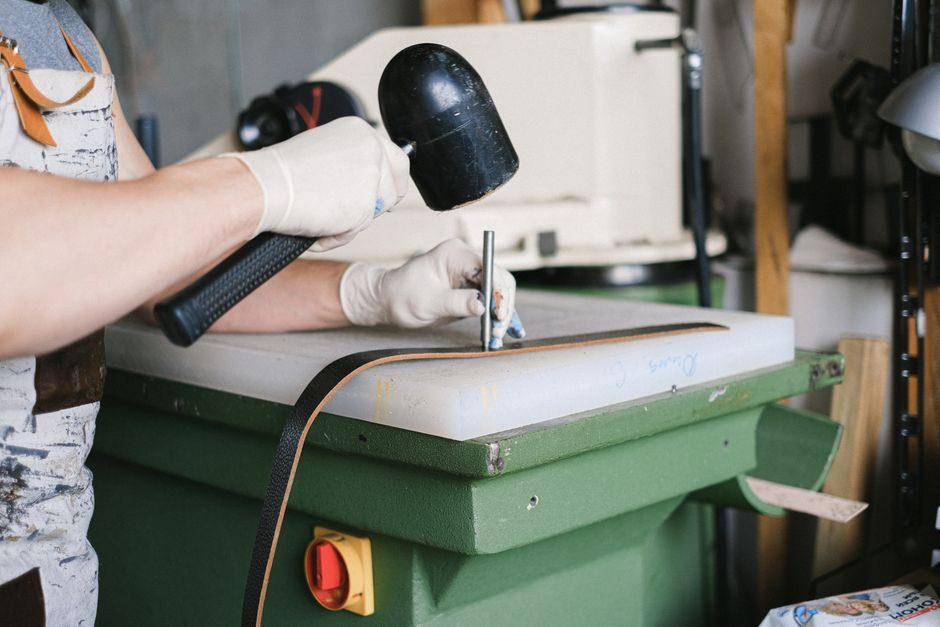
Use a soft-brass drift, never a steel hammer, to seat the R-bushings; lubricate the leader pins with Molykote D-321R or equivalent dry-film graphite before the first close so break-in wear deposits on the pin, not the bushing. The R-bushing is the wear part on a standard mold base: replace at 0.06 mm measured ID growth, not at "looks worn." For tooling that routes melt through a casting mold interface or a sand-cored insert, hold the same 0.02-0.04 mm window so core shift does not double up on the casting tolerance stack [S3].
Clamp-Foot Torque Sequence and Bolt Class

Mold-base clamp feet must be torqued in a star pattern (1-3-2-4 sequence on a 4-bolt base) at 35-45 Nm on M16 class 8.8 socket-head bolts for a 600-800 t press; this generates 0.8-1.0 t of clamp preload per bolt, which is what resists the die-open force during injection without stripping the T-slot. [S3]
Use only the press manufacturer's spec sheet for clamp force versus shot pressure, and verify the clamp foot shim stack is 0.1-0.3 mm total so the mold base sits flat without rocker; a 0.5 mm shim gap lets the mold rock under peak clamp, which shears the leader pin at the parting line. Re-torque after the first 200 shots when the mold base reaches steady-state temperature, because the steel expands differentially and the initial cold-torque relaxes 8-12 % [S3].
Ejector-Plate Reset, Parallelism, and Return-Spring Preload
Ejector-plate parallelism must hold within 0.05 mm across the full plate span; out-of-parallel plates tilt the ejector pins, which then scrape the core inserts and produce score marks visible on the first molded part. [S3]
Set return-spring preload at 10-15 % of the full stroke compression so the ejector plate returns cleanly against the stop pins before the mold closes; weak springs (below 5 % preload) let the ejector hang in the open position, smashing pins into the cavity at close. Stroke the ejector manually three times with the clamp foot bolts loose, then once with full clamp, to confirm no bind; the mold base standard-parts list specifies stop-pin length, return-spring part number, and ejector-pin clearance all in one callout, so do not mix supplier SKUs without re-verifying the parallel-spring constant [S3].
Parting-Line Coplanarity and Flash Prevention
Parting-line coplanarity between cavity retainer plate and support plate must read under 0.03 mm at four corners on a surface plate; above 0.05 mm, a standard ABS shot at 900 bar will flash 0.1-0.3 mm along the parting edge, which is the most common first-shot failure on a new mold-base install. [S3]
Scrape the parting line with a diamond stone, never a file, and recheck flatness after scraping. For high-pressure applications (thin-wall packaging, glass-filled resins) the coplanarity budget tightens to 0.015 mm and a vent-depth check at 0.005-0.015 mm is mandatory. For tooling that stacks a die-casting die half onto the same press, hold the same coplanarity discipline because thermal growth on a die-cast cycle adds another 80-100 µm of parting-line drift per cycle.
Acceptance Test: 50-Shot Sign-Off Protocol
The mold-base sign-off runs 50 cold-start shots plus 200 production shots with full process monitoring: parting-line flash inspection every 10 shots, leader-pin temperature rise below 15 °C above platen, and ejector-pin return confirmed by feeler gauge at the parting line.
Record the clamp-foot torque on the work order after the 200-shot mark, because creep relaxation in the first 200 shots settles the bolt preload to its working value. If leader-pin temperature rises above 20 °C steady state, the bushing fit is too tight and the mold base must come out for reaming. For shops running industrial robot cells on the take-out, also verify ejector-park position sensor output and robot pick-up coordinate repeatability within 0.1 mm before releasing the tool to production.
Common Failure Modes and When to Replace, Not Repair

Replace, do not repair, when R-bushing ID growth exceeds 0.06 mm, when leader-pin entry chamfer shows visible peening, or when the clamp-foot T-slot has been deformed by over-torque above 60 Nm on M16 class 8.8 these are not field-repairable conditions on a standard mold base. [S3]
Scrape-and-retry is acceptable only on parting-line coplanarity up to 0.05 mm and on ejector-plate parallelism up to 0.08 mm. Worn ejector-pin holes above 0.05 mm clearance require bushing replacement, not pin replacement; the hole is the wear surface, not the pin. Track the next service interval by shot count rather than calendar time: standard mold-base service life is 250 000-400 000 shots for unfilled PP, dropping to 80 000-120 000 for glass-filled PA66, and the first 10 000-shot walk-through is the cheapest insurance against the leader-pin / bushing / clamp-foot failure cluster.
Next signal to track: any leader-pin surface temperature above 20 °C steady-state on the first 50-shot acceptance run, which forces a re-bush and re-fit before the tool enters the production fleet.
Spec-level background on the components involved: linear guide.