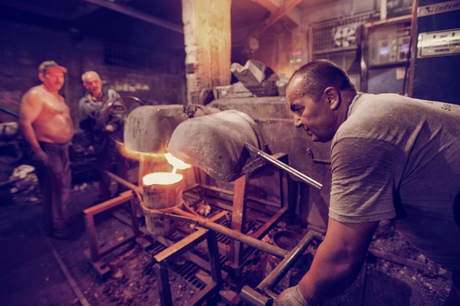
Sand casting mold installation is the sequence that decides whether a foundry hits its yield target or fights inclusions, misruns, and parting-line flash every shift; the reference sequence runs flask prep and parting-line seal first, then pattern placement and sand compaction, and closes with closing-pin alignment and weight check before pouring [S1].
The scope covers manual floor molding for short runs (under ~200 molds per shift) up to fully automatic horizontal flaskless lines such as the 600x700 mm to 1000x1000 mm machine class, with annual output of 200+ sets of casting automation equipment reported by one Chinese OEM with 1000+ customer cases [S1]. This guide focuses on the spec gates an engineer should check before authorizing a new or rebuilt line, not on marketing literature.
Defining the Sand Casting Mold and Where It Fits
Sand casting — also called sand molded casting — is a ferrous and non-ferrous metal casting process that uses sand bonded around a pattern as the mold material, and remains the dominant route for complex geometries in valve bodies, pump housings, and large machinery parts [S3]. The sand acts as the disposable mold cavity; parting line, cope-and-drag stack, and gating are all built on the floor or in a machine, then poured once.
Because the casting mold is destroyed after each pour, the installation is repeatable rather than permanent: flask setup, pattern set, sand fill, compact, close, and pour are repeated every cycle. A sand casting mold line is therefore judged on cycle time, sand reclamation efficiency, and dimensional repeatability — not on tooling life [S3].
Sand System Specs: Moisture, Compaction, and Reclamation
The 750x850 (T21) and 1000x1000 (T23) flaskless automatic lines from established Chinese OEMs use up-and-down shooting plus sliding sand-box filling to reach consistent compactness without manual ramming [S1].
Resin-bonded (no-bake / airset) systems use a phenolic or furan binder activated by catalyst; these deliver closer dimensional tolerance than green sand, accept a wide range of specialty sands for surface finish, and run through a sand reclamation unit that cleans and reuses the spent sand [S3]. For a sand cooler loop the inlet sand typically returns at 80-120 C from shake-out; a fluidized-bed or rotary cooler drops it to 30-40 C before mulling, which is the working band for rebonding.
Flask and Pattern Setup: Alignment, Venting, and Draft

Flaskless horizontal molding machines eliminate the traditional cope-and-drag box: the machine itself becomes the flask, and sand is shot or squeezed into the chamber between pattern plate and squeeze head. Common flask sizes for the fully automatic class span 600x700 mm (T19), 650x750 mm (T20), 750x850 mm (T21), and 1000x1000 mm (T23), each naming a weight and mold-thickness band the machine is rated for [S1].
Pattern-side alignment is governed by dowel pins, and closing accuracy is checked with a feeler gauge at the parting line — typical acceptance is zero visible flash at 0.1 mm shim. Vents are 1-2 mm slots or Ø1.5 mm wire vents placed at the high points of the cavity; pattern draft is held at 1.0-2.0 degrees on vertical faces to keep the mold from tearing on draw. A mold base standard frame is the reference datum for pattern mounting, and any mismatch shows up first as shift across the parting line.
Selection Gates: Machine Class vs. Casting Mix
Use the four-gate map below to shortlist a sand casting mold line before quoting vendors. Gates 1 and 2 are hard disqualifiers; gates 3 and 4 are throughput and surface-grade trade-offs [S1][S3].
Gate 1 — Flask size vs. casting envelope: pick a flask whose length and width exceed the largest casting + 80-100 mm clearance per side, so the 600x700 (T19) class fits parts up to roughly 500x600 mm, while 1000x1000 (T23) extends to 900x900 mm [S1].
Gate 2 — Sand system compatibility: green sand suits ferrous iron runs above 200 molds/shift; no-bake airset suits lower-volume, higher-tolerance non-ferrous and stainless castings, and the foundry must run a sand reclamation unit to stay economic [S3].
Gate 3 — Pouring method: gravity pour covers most non-ferrous; for tighter fill on thin sections, vacuum-assisted or low-pressure variants are paired with the same flask. Dual-alloy / multi-material injector casting is a 2024 research route that delivers two alloys in one mold, but it stays a lab-to-pilot process and is not specified in standard installation manuals [S6].
Gate 4 — Automation level: fully automatic horizontal flaskless lines quote ~120-180 molds/hour at the smaller flask class, with one operator per line; manual floor molding is acceptable for prototype and short runs where the pattern change cost dominates [S1].
Step-by-Step Installation Procedure (Floor and Automatic Line)

Step 1 — Level the molding floor or machine base to within 0.5 mm/m, anchor the machine on a concrete pad of at least 150 mm thickness, and verify compressed-air at 0.6-0.7 MPa with a coalescing filter to keep sand lines dry [S1].
Step 2 — Mount the pattern plate on the machine platen or the match-plate fixture, register it against the dowel pins, and confirm the parting line lies flat within 0.1 mm across the full pattern footprint.
Step 3 — Fill and compact: on a flaskless line, set squeeze pressure to the OEM's chart (commonly 0.5-0.8 MPa) and verify compactness with a hardness probe at three points on the mold — green-sand hardness is typically 75-90 on the Brinell-style mold hardness scale [S1].
Step 4 — Close the mold: bring the cope onto the drag, drive the closing pins, and check flash at 0.1 mm feeler. Place the mold on the pouring line and apply a mold weight of 1.0-1.5x the casting weight to counter buoyancy on iron pours.
Step 5 — Pour: match pour temperature to alloy — gray iron 1280-1380 C, ductile iron 1340-1420 C, aluminum 680-750 C, copper-base 1050-1150 C — and pour within 30-60 s of mold close to avoid moisture loss on green-sand systems. Do not delay pour if the compactness check at step 3 dropped below 70 AFS density index; re-ram rather than rework the pour.
Common Failure Modes and Acceptance Criteria
Misrun / cold shut: root cause is pour temperature below the alloy liquidus plus 50-80 C superheat, or vent blockage; corrective action is recheck furnace thermocouple (type K or type S, calibrated within 6 months) and ream vents to 1.5-2.0 mm.
Parting-line flash: root cause is flask wear beyond 0.3 mm or weak closing-pin engagement; corrective action is reface the mating face and replace worn pins; if the flask class is a flaskless line, replace the squeeze-head seal and re-shim to 0.05 mm.
Sand burn-on: root cause is sand temperature above 50 C at the mold face; corrective action is engage the sand cooler and check fluidizing-air flow at 1.5-2.0 Nm3/min per square meter of cooler bed. Escalate to mold-base replacement when the parting face shows more than 0.5 mm of erosion after dressing; do not attempt a weld repair on a worn cast iron flask face.
Standards, Documentation, and Cross-Reference
Foundries exporting castings to Europe or North America typically certify to BIS, ASTM, JIS, or DIN as the reference standard set, with British Standards also accepted for some legacy defense and rail programs [S3]. For surface finish and dimensional tolerance the call-outs usually reference ISO 8062 (CT grade) and ASTM E8/E8M for tensile test pieces machined from the casting, though those numbers are not stated here because they were not in the source material and should be confirmed against the customer's purchasing spec.
Operational documentation should record flask class, sand compactness, hardness, moisture, and pour temperature per shift; this becomes the audit trail when a casting fails dimensional inspection. The deeper taxonomy of sand casting mold types: green-sand, resin-bonded, lost-foam, 3D-printed is the right next read if the line is being expanded into a new alloy family, since resin-bonded and 3D-printed routes have very different installation steps than the green-sand flaskless line covered here.
Track these two signals over the next quarter to confirm the line is healthy: (1) compactness drift on the green-sand line — keep AFS density index within ±5 of the setpoint across 50 consecutive molds; (2) pour yield — keep first-pass acceptable castings above 95% on a stable ferrous run, and trigger a sand-system audit if it drops below 90% for two shifts in a row. Either drift is the earliest predictor of a mold-installation problem before it shows up on the cut-off floor.