
Modern motor protection relays accept up to 6 or 10 RTD inputs (Pt100, Pt1000, or Ni100) and use them as a second thermal channel layered on top of the calculated I²t model from the phase CTs, per motor management relay practice documented across multiple OEM datasheets [S1][S7].
The relay does not derive stator temperature from current; it reads actual copper temperature from a resistance element embedded in the slot, so trip and alarm setpoints are written in °C against insulation class limits (Class B 130°C, Class F 155°C, Class H 180°C) rather than as a percentage of full-load amps [S2][S4].
RTD Element Types and Slot Construction
Stator-slot RTDs come in two element constructions: wire-wound (extends through most of the body length and averages the winding temperature) and thin-film (a small sensing area of roughly 2.0 mm × 2.3 mm that reads one localized spot) [S4]. The Minco S100 series datasheet specifies a temperature limit of -50 to +180°C (Class H), 3,200 V RMS dielectric strength at 60 Hz between leads and body, AWG #22 stranded copper leads with TFE or polyimide insulation, and a body of high-temperature epoxy glass [S4].
Two-, three-, and four-lead RTD wiring is offered, with the 4-lead configuration required when lead resistance would otherwise push Pt100 accuracy out of IEC 60751 Class A or Class B tolerance; the 4-lead minimum body width is 7.25 mm versus 5.6 mm for 2- or 3-lead units, so the slot geometry has to accommodate the wider package [S4]. Sensor lengths span 2.0 in (51 mm) to 23.2 in (590 mm), and ATEX/IECEx-certified versions carry EC-Type Examination Certificate KEMA 03ATEX2240 U for II 2 G Ex e IIC Gb and II 1 G Ex ia IIC Ga hazardous-area mounting [S4].
How Many RTDs, and Where They Sit
For medium-voltage motors (4.16 kV class), 6 embedded RTDs is a common configuration: two per phase, distributed along the slot to catch localized hot spots and to provide redundancy if a single element fails [S3]. One experienced protection engineer notes that 90% of single-RTD "way-out-of-line" high readings on a 4160 V, 2,300 hp machine turn out to be a failed element, which is itself a reason utilities and plant operators specify 6 rather than 3 RTDs [S3].
The relay then takes the highest of the six readings (or an average, depending on the selected algorithm) as the alarm and trip input; for example, the GE Multilin 239 platform accepts a standard motor-temperature thermistor input plus three additional 100 Ω platinum RTDs located in the stator and/or bearings, and trips are mapped to either winding or bearing setpoints [S7]. On large HV machines, dual-element RTDs (two independent sensing elements in one body) are used to extend the average-length reading while still surviving single-element failure, with corona-resistant variants available for the line-end coil of medium-voltage stators [S4].
RTD Channel Specs Inside the Relay

Typical protection-relay RTD input channels accept 100 Ω platinum (Pt100) at 0°C, with a nominal 0.385 Ω/°C temperature coefficient per IEC 60751, and auto-range to cover sub-zero ambients to Class-H hot spots [S2][S4]. The relay converts resistance to temperature using a lookup or Callendar-Van Dusen polynomial, then applies user-defined stages: usually an Alarm at, for example, 130°C (Class F warning) and a Trip at 145°C or 155°C depending on the insulation rating, with separate setpoints for the three bearing RTDs (drive-end, non-drive-end, and a third bearing on large machines) [S1][S2].
Open-circuit (broken lead) and short-circuit detection is standard; the relay forces a trip on sensor failure rather than allowing the channel to read ambient as a false "healthy" value, because an undetected open RTD on a 4.16 kV motor would silently disable the only direct stator-temperature channel [S3][S7]. A practical field observation: during a motor start, the RTD in the slot lags the copper hot-spot because the sensor is mounted outside the turn insulation, so a relay that relies on RTD alone for thermal protection will under-protect during locked-rotor and acceleration conditions; the correct layering is a thermal model from the phase CTs for the start transient plus the RTD channel for running overheat and ventilation-loss conditions [S3].
Selection Criteria: Wire-Wound vs Thin-Film, 3-Wire vs 4-Wire
Wire-wound stator RTDs average temperature across roughly the full body length and are preferred on large machines with long slots, where a single thin-film spot could miss a localized heating zone [S4]. Thin-film elements (about 2.0 mm × 2.3 mm) are used on shorter slot sensors where spot-reading is acceptable and the smaller package is easier to fit between top and bottom coil sides [S4].
Lead configuration is driven by cable length: 2-wire is acceptable only for short lead runs where the lead resistance is negligible versus the 0.385 Ω/°C slope; 3-wire (the most common in motor protection) cancels lead resistance with a single compensation loop; 4-wire is specified when lead resistance plus ambient drift could exceed Class A tolerance (IEC 60751 ±0.15°C at 0°C) over long cable runs from the motor junction box to the relay panel [S4]. The relay itself must support the chosen wiring; entry-level motor protection relay units may offer only 3-wire inputs, while microcomputer protection platforms expose 4-wire RTD channels for higher-accuracy thermal biasing.
What RTD Protection Does Not Catch
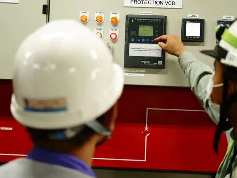
Stator-winding ground faults are the most costly failure mode on HV motors, and RTD-based thermal protection is not designed to detect them; the relay's differential or ground-fault overcurrent element covers that risk separately, which is why HV motor protection schemes always layer a 51N or 50N ground element on the CT secondary in parallel with the thermal/RTD channel [S5]. The same source flags that RTD readings are a lagging indicator during locked-rotor starts because the embedded sensor cannot follow the rapid copper temperature rise inside the turn insulation within the first few seconds of a stalled start [S3][S5].
Other failure modes the RTD channel will miss or misinterpret: ventilation loss on a totally enclosed fan-cooled motor (the RTD reads a real rise, but only after the rotor and stator have already overheated, and only if the affected RTD is downstream of the blockage); single-phase supply loss on a running motor (negative-sequence heating shows up in the stator only after several minutes, and a 3-RTD scheme may read average instead of phase-to-phase imbalance); sensor failure producing a mid-scale or open-circuit reading that the relay must be configured to treat as a fault, not as a "cool" reading [S3][S7]. The general rule, repeated by experienced protection engineers on the control.com forum, is that RTDs are not a primary protection element on HV motors; they are a backup and a trending instrument, layered behind overcurrent, differential, and ground-fault functions [S5].
Commissioning and Trending
On a 6-RTD scheme, commissioning typically logs all six resistance values at ambient (a healthy Pt100 reads 100.00 Ω at 0°C, about 107.79 Ω at 20°C, and about 119.40 Ω at 50°C per IEC 60751), then verifies that the relay's displayed temperatures match within ±2°C of a calibrated bench RTD or handheld calibrator at one or two spot temperatures [S4]. Insulation resistance of the RTD lead to ground is checked with a 500 V megohmmeter; readings below 100 MΩ on a winding-embedded sensor indicate moisture ingress into the slot and the need to schedule a motor outage for re-varnishing or sensor replacement [S4].
For long-term trend monitoring, modern relays expose each RTD channel to the plant SCADA via Modbus TCP, IEC 61850, DNP3, or PROFIBUS, with a typical logging resolution of 1°C and a 1-minute sample, so insulation aging shows up as a slow upward drift in the running-temperature baseline well before a hot-spot trip [S7]. The RTD Pt100 sensing principle, in which resistance rises monotonically with temperature, is what makes that slow-drift trending feasible: a baseline shift of 5°C over 12 months is a real maintenance signal, not a sensor artifact, and it lets the operator schedule a cleaning or rewinds before a forced outage. For hazardous-area motors, the relay-side zener barriers or galvanic isolators must be rated for the same Ex i entity parameters as the ATEX/IECEx-certified RTD (KEMA 03ATEX2240 U) to keep the intrinsic-safety loop compliant end-to-end [S4].
Related Reading and Trackable Signals
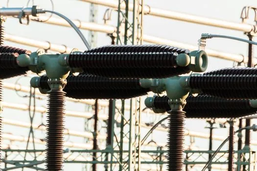
For hazardous-area motor circuits, the practical settings and coordination study of a motor protection relay running with embedded stator RTDs is laid out in the Motor Protection Relay for Hazardous Area Motor Circuits reference, which complements the sensor-side detail above with the relay-side setpoint logic. Two signals worth tracking over the next quarter: (1) more relay vendors offering 10-RTD channels as standard on MV-class motor management units, which would let the 6-RTD scheme extend to dual-element coverage on each phase end-coil; and (2) wider adoption of IEC 61850-9-2 sampled-value reporting for per-RTD temperature, which would let a temperature controller or plant asset-health platform trend each sensor individually instead of relying on the relay's internal "max-of-six" logic [S2][S4].