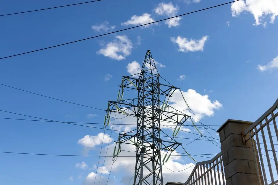
Medium-voltage motor protection relays typically cost 3–8x more than low-voltage units, driven by instrument transformers, differential (Device 87) schemes, and switchgear integration rather than relay electronics alone [S5][S2].
The crossover point sits near 250 hp and 1000 V: below it, conventional LV thermal overloads cover most fault modes; above it, differential protection, ground-fault sensing, and VT/CT signal conditioning become mandatory for safe operation [S2][S5].
Voltage classes and the hp crossover
Medium-voltage motors in industrial practice span 1 kV to 15 kV AC, with common ratings of 2.3 kV, 4.16 kV, 6.6 kV, and 13.2 kV, while low-voltage units sit at or below 1000 V [S7]. The hp boundary is not a single number: ABB cites 1000 hp as the typical upper limit for LV induction motors, with MV starting around 250 hp, and competitive MV/LV overlap between roughly 250 hp and 1500 hp depending on speed, enclosure, and starting method [S2].
Royal OEM references put the practical "default" LV ceiling near 400 kW for general-purpose machines, with the higher cost of MV switchgear and cabling offset by lower running current and smaller conductor cross-section at higher power [S6]. The economic break-even therefore depends less on relay sticker price and more on feeder, transformer, and cable sizing across the full Bill of Materials [S2][S6].
Why MV relays cost more than LV relays
Instrument transformers dominate the price delta. Standardised secondary ratings of 120 V on voltage transformers and 5 A on current transformers are required because the relay itself cannot be wired directly to 4.16 kV or 13.2 kV bus potential, and these VT/CT pairs are priced per phase [S5]. A complete MV motor cell therefore includes one VT assembly, three to six CTs, the motor protection relay, a circuit breaker (air, SF6, or vacuum), and the switchgear housing, and that full assembly is the right unit of cost to compare against a simple LV thermal overload block [S5].
Functional content is also heavier. MV schemes add Device 87 differential protection, residually connected ground-fault relaying, and current-unbalance (split-winding) supervision, each of which requires more inputs, more logic, and more panel wiring than a basic LV overload [S5]. Relay electronics are a small share of total cost; the auxiliary transformers, CTs, panel space, and commissioning labour are the real cost drivers in a 4.16 kV motor cubicle [S1][S5].
Decision matrix: LV relay vs MV relay package

Four criteria separate the two. (1) Voltage class: at or below 1000 V, an LV relay is the only legal and economic option; at 2.3 kV and above, MV instrument transformers and switchgear are mandatory [S7][S5]. (2) Motor rating: below 250 hp, LV dominates; between 250 hp and 750 kW, either can be applied but LV thermal-class overloads remain common; at 750 kW and above, especially above 2400 V, differential protection is recommended and a microcomputer protection relay with multiple Device 87 elements becomes standard [S5]. (3) Fault exposure: MV motors are electrically closer to the utility source, so they see higher available fault current, more voltage sags, and reclosing transients, and a basic LV thermal block cannot coordinate with downstream MV fuses under those conditions [S5]. (4) Total installed cost: the relay itself is only part of the bill; CTs, VTs, panel space, and cabling typically multiply a 1x LV relay cost by 3–8x once you reach a complete MV motor cell, while LV installations stay close to the relay sticker price [S1][S5].
Selection criteria for the relay itself
Specify the relay by the fault modes you need to clear, not by feature count. For LV motors under 250 hp, a thermal-class electronic overload with phase-loss, phase-reversal, and adjustable current range typically covers the required protection [S2][S5]. For MV motors, the minimum credible scheme is a protection relay that handles definite-time overcurrent, ground fault (residually connected CTs), and current unbalance, with differential as an add-on for critical or high-horsepower units [S5].
CT and VT secondary ratings must be locked at 5 A and 120 V respectively so the relay can interface with standard switchgear, and the CTs must be sized to carry full-load current continuously without saturating during an external fault [S5]. Above 2400 V, differential protection becomes easier to justify because a winding fault cleared in milliseconds costs far less than a rewind or a replacement, so the relay's analogue input accuracy and the CT's burden specification are not optional [S5].
Where LV is still the right answer
Stay with LV relays when the motor sits at 400 V or 690 V, when the driven load is not critical to a process unit, and when the upstream breaker already provides short-time overcurrent coordination. Standard NEMA and IEC LV motor starters with electronic overloads are widely used, easily replaced, and stocked by every industrial supplier, which keeps spares cost and mean time to repair low [S2][S3].
For installations already configured around medium-voltage VFD cells or soft-starters, the relay cost is a small share of the cell, and the right move is often to keep the relay family consistent with the VFD's built-in protection rather than mixing LV and MV relay brands across the lineup [S2][S8].
Limits, failure modes, and standards reality
Classic induction-type overcurrent relays, the kind still found in older cement and mining plants, are limited in their ability to distinguish between a locked rotor and a real fault, which is one of the main engineering arguments for upgrading to a microprocessor-based relay on existing MV motors [S1]. Differential protection avoids the problem by comparing line-side and neutral-side current directly, but it requires six CTs and a balanced wiring layout, and that balance shifts with cable length and CT polarity, so commissioning crews must verify polarity and ratio on every retrofit [S5].
Two practical constraints govern the spec. First, ground-fault protection on an MV system needs a properly designed neutral grounding resistor, and the resistor value sets the relay pickup; a relay set without that coordination will either nuisance-trip or fail to detect a real ground fault [S5]. Second, MV motors are more exposed to utility-side transients, surge, and reclosing, so surge arresters and a relay with adequate VT surge withstand are part of the same protection package, not optional add-ons [S5].
Use cases and pricing reality check

For a 100 hp, 460 V pump, an LV thermal electronic overload typically lists at a fraction of the cost of a comparable MV relay, and the rest of the motor cell (contactor, breaker, panel) stays small. For a 1500 hp, 4.16 kV compressor, the relay electronics are again a small line item, but the CTs, VTs, and switchgear cubicle push the total motor-cell cost many times higher, and trying to substitute an LV relay there is not legal, not coordinated, and not safe [S2][S5][S7].
The clearest trackable signals to watch: published list prices on the dominant relay families, changes to the 2400 V differential-justification threshold in vendor technical guides, and any move by utilities to tighten reclosing or sag ride-through requirements on industrial MV feeders, since each of those shifts the LV/MV cost curve [S5]. Fail-safe trip wiring remains the most overlooked cost line on MV retrofits, and multi-turn primary CT loops are the most common spec fix when small LV motors are upgraded with a modern numerical relay.