
A motor protection relay in a hazardous area has to clear the motor before the winding surface exceeds the certified temperature class, not just before the insulation fails; a T4-class machine permits a maximum surface temperature of 135 degrees Celsius in normal operation and under fault conditions [S3].
For Zone 1, Zone 2, Division 1 and Division 2 motors, the relay setting is anchored to the nameplate full load current at the actual operating voltage, with the overload pickup converted to secondary current through the installed CT ratio, and the upstream protection relay sized to discriminate with the contactor on locked-rotor current [S3][S4].
Why Hazardous Area Relays Are Not Set Like General Purpose Relays
A general purpose motor protection relay is sized to protect the winding insulation; a hazardous area relay is sized to keep the enclosure and the winding surface below the ignition temperature of the surrounding gas or dust cloud, so the available thermal headroom shrinks dramatically [S3][S8]. A T4 motor running at full load sits close to its permitted surface limit, and a 10 percent overload applied for an extended period pushes the surface above 135 degrees Celsius, breaking the area classification regardless of the enclosure rating [S3]. Setting the pickup from a busbar schedule prepared for a non-hazardous utility block is the most common audit finding in chemical and pharmaceutical plants [S3].
The fault envelope is also different. Hazardous area motors are often started against a high pressure or viscous load, run at reduced ventilation, and stalled inside vessels or mixers, all of which tighten the setting rather than loosen it [S3]. The relay must therefore use the motor's 1.0 service factor, even when a safe-area machine of the same frame is rated 1.15, because the temperature class is only certified for the published nameplate current [S3].
Overload Pickup, CT Ratio, and Service Factor Discipline
Overload pickup is set to motor nameplate full load current at the actual operating voltage, with no service factor added unless the manufacturer's certified nameplate expressly permits it [S3]. With a 100/1 CT on a 47 A motor, the secondary pickup entered in the relay is 0.47 A, and the most frequent field error is entering the CT ratio as 100 rather than 100/1 or selecting the wrong CT tap [S3]. Protection class CTs are preferred for short-circuit detection, but metering class CTs are still common in legacy switchgear; if the CT saturates, the relay cannot see the true short-circuit current and discrimination with the upstream circuit breaker collapses [S3].
Where the nameplate carries a service factor above 1.0, the relay should still default to nameplate full load current until the temperature class certificate confirms the higher overload is covered; on North American explosion proof motors, a 1.15 service factor does not automatically extend the T-class envelope [S3]. When the documentation is silent, treat the service factor margin as zero additional relay pickup [S3].
Short-Circuit, Locked-Rotor, and Coordination With the Contactor
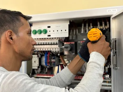
Short-circuit pickup is set above the motor's locked-rotor current at the relay terminals, not at the busbar, and the instantaneous element is verified against the contactor's let-through and the upstream breaker's short-time band so the contactor never tries to break a fault the breaker is supposed to clear [S3][S4]. Single-phasing protection is mandatory on three-phase hazardous area motors because an open phase drives the remaining two windings into a sustained 1.5x current with reduced ventilation, a combination that pushes the surface past the certified limit long before a general purpose overload trips [S4]. Earth-fault protection, typically set at 30 mA for personnel or 10 to 30 percent of full load for equipment protection on insulated systems, is added where the installation uses an IT or impedance-earthed scheme [S4].
Locked-rotor and starting-time protection is sized from the motor's thermal limit curve, with a stall trip that opens the contactor within the certified locked-rotor withstand time, typically 5 to 15 seconds for small and medium motors, and a separate acceleration timer that distinguishes a normal start from a stall [S4][S5]. A stalled impeller in a Zone 1 pump can heat the winding from ambient to the T-class limit inside a single starting attempt, so the relay must use the manufacturer's thermal limit curve, not a generic 10-second rule [S3][S5].
Thermistor and PTC Winding Protection in Ex e Motors
For increased-safety (Ex e) motors, the winding is monitored directly by PTC thermistors that feed a thermistor motor protection relay such as the ABB CM-MSS range, which trips the contactor when the sensor resistance crosses the rated response temperature, typically 130, 150 or 180 degrees Celsius for Class F or H insulation [S1]. The CM-MSS family handles one or three PTC sensor chains, with a separate output relay for alarm and trip, and the response is independent of the current-based overload element so a stalled, lightly loaded motor is still caught [S1].
Stall-safe design uses PTC sensors in the end-windings and a short-circuit loop inside the motor so a sensor or cable failure forces the relay into the safe (trip) state, matching the Ex e requirement that a single protection function failure cannot leave the motor unprotected [S1]. For Ex d and Ex t motors, the surface temperature is enforced by the enclosure and the T-class certificate, so thermistor protection is an extra layer rather than the primary limit, but the same CM-MSS relay is still widely fitted because the sensor also catches blocked-filter and dry-running faults that do not appear in the current signature [S1][S2].
Ex e Certified Modules: R. Stahl Series 8510 and Comparable Designs
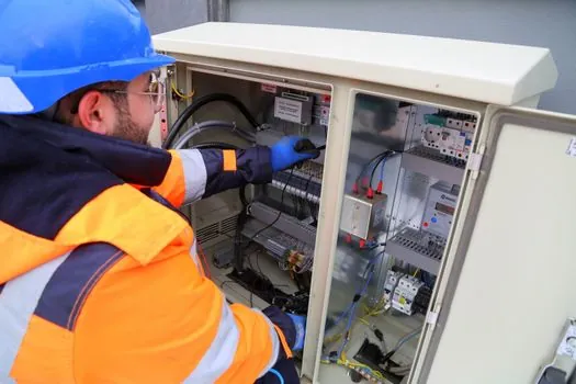
The R. Stahl Series 8510 motor protection relay is supplied as a cost-effective overload module for Ex e motor circuits, with a release current that is easy to adjust and reset, a robust enclosure rated for vibration, and a terminal layout designed for Ex e terminal boxes installed on or near the motor [S2]. The module is paired with Ex e motor protection circuit breakers, DOL motor starters, star-delta starters and soft starters in the same product family, so the overload element, the contactor, and the wiring all share the same Ex e certification and the same creepage and clearance data [S2].
Thermistor-based R. Stahl relays in the same family add direct winding-temperature monitoring through PTC sensors, and a stalled-rotor condition inside a Zone 1 pump is detected by the PTC chain even when the current-based overload is still inside its band [S2]. Selecting the relay from the same Ex e family as the breaker and the contactor removes the cross-certification work that delays hazardous area retrofits, because the installer can rely on a single set of type-test documents [S2].
Comparison of Relay Options Against Selection Criteria
Four common relay options for hazardous area motor circuits are lined up against five selection criteria. Thermal-only overload relays are cheap, simple, and proven, but offer no earth-fault or thermistor input, so they are confined to small, non-critical motors in Zone 2 [S4]. Current-based electronic motor protection relays add phase loss, phase imbalance, under-voltage, and ground fault, with selectable trip classes 5, 10, 20 and 30, and dominate Zone 1 and Zone 2 LV motor control centres [S4][S5]. Intelligent relays with communication, such as the Blue Jay PR series, add MODBUS or PROFIBUS, RTD inputs, and event logs, and are specified for motors above 75 kW or where unplanned-downtime cost exceeds USD 10,000 per hour [S5][S7]. Thermistor-only relays such as the CM-MSS are mandatory on Ex e motors above 11 kW in IEC-aligned installations because the certificate requires direct winding-temperature monitoring, and they sit alongside a current-based overload rather than in place of it [S1].
Cost ranges track function: a thermal-only module is typically USD 80 to 200, an electronic motor protection relay is USD 250 to 800, an intelligent relay with fieldbus is USD 600 to 2,500, and a CM-MSS-class thermistor relay is USD 150 to 400, with Ex e-certified enclosures adding a 30 to 80 percent premium over the safe-area equivalent [S1][S2][S7]. On a 22 kW Ex e pump in Zone 1, the typical bill of materials is an Ex e motor protection circuit breaker, a CM-MSS thermistor relay, a current-based electronic overload, an Ex e contactor, and a control terminal box, all sourced from one Ex e family to keep the certification documents aligned [S2].
Standards, Documentation, and What to Check Before First Start
The hazardous area classification, Zone 1, Zone 2, Division 1, Division 2, and the gas or dust group, A, B, C, D, IIA, IIB, IIC, IIIA, IIIB, IIIC, are fixed before the relay is selected, because the temperature class T1 to T6 governs the relay setting as much as the motor setting [S3][S8]. The relay's certificate (ATEX 2014/34/EU, IECEx, or UL Class I Div 1) must match the area classification, and the relay's ambient temperature range, typically minus 20 to plus 60 degrees Celsius for industrial units, must cover the cabinet interior [S1][S2].
Before first start, the commissioning engineer checks the nameplate FLC against the entered pickup, the CT ratio and tap, the service factor treatment, the locked-rotor curve, the contactor and breaker discrimination, and the PTC loop resistance at room temperature, then logs the relay's event buffer and the measured insulation resistance on the motor and the feeder [S3][S4]. The microcomputer protection class relays store a fault waveform on every trip, so the first fault event is recoverable as a COMTRADE file rather than a verbal site report [S5]. Where thermistor monitoring is fitted, the loop resistance is recorded cold and at the PTC response temperature, confirming the relay trips on the sensor chain and not on a current-derived estimate [S1].
Trackable signals to watch in the next planning cycle: motor copper and steel input costs that reset Ex d and Ex e motor price lists every quarter, and small-motor CT-loop retrofit demand for compact industrial relay retrofits in legacy motor control centres. For copper and steel-driven motor pricing dynamics, see 2026 Electric Motor Pricing: Copper, Steel, and Nine Cost Dials; for small-motor CT-loop wiring practice, see Multi-turn primary CT loop for small motor protection relays; and for the broader Ex e component ecosystem around the relay, see 316L Stainless Steel Camera Housing for Offshore Corrosive Sites: Spec, Compliance.