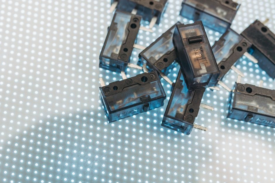
A 1/2–2 HP single-phase motor protector (C-UL, manual push reset) and a 5 m/s coreless linear motor module (80 mm base, 1400 mm stroke) sit at opposite ends of the motion-control bill of materials — one is a safety component sized in amps, the other is a precision stage sized in micrometres [S2][S4].
Specifying one where the other belongs is the single most common engineering error in compact-machine retrofit work; the two products share no interchangeable duty, no common rating system, and no shared sizing equation.
What Each Device Actually Is
A motor protector is a thermal-magnetic disconnect built around a bimetallic strip and an instantaneous magnetic trip coil; the Fuji BM3RHB-6P3 carries a 4.0–6.3 A adjustable thermal range with an 81.9 A instantaneous trip rating in a 45 mm frame, while the BM3VHB-010 steps that to 6.3–10.0 A adjustable / 130 A instantaneous in a 55 mm frame [S5][S7].
A linear motor is an unrolled stator that produces thrust directly along a travel axis without leadscrew, belt, or rack-and-pinion conversion; the HIWIN SSA08 standard module delivers a 5 m/s top speed over a 1400 mm effective stroke from an 80 mm-wide base with a 107.5 mm forcer [S2]. Coreless (ironless) and iron-core variants behave differently — coreless designs eliminate cogging and are preferred where velocity ripple would otherwise contaminate a positioning loop.
Current and Force: The Numbers That Separate the Two
Motor-protector ratings are quoted in amperes on a thermal scale with a separate magnetic instantaneous trip — for example, 10 A thermal / 130 A instantaneous on the BM3VHB-010, which is roughly 13× the continuous rating [S7]. A linear linear actuator is rated in newtons and millimetres per second; the MATLAB Simscape reference model uses a 24 V DC motor with a 6.25:1 worm gear and 3 mm lead screw producing 1000 N rated load at 19 mm/s and a 4000 N static force at 5 A locked-rotor current [S1].
That single data set maps the two domains: protector current (amperes) and linear-motor force (newtons) are not interchangeable, and force-per-ampere is derived from torque constant — in the reference model, Kt is 0.066 N·m/A computed as (4000 N × 3 mm pitch / (2π × 6.25 gear)) / (5 A − 0.35 A no-load) [S1].
Decision Criteria Side-by-Side
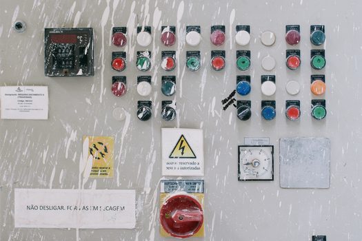
The four criteria that govern any comparison: (1) function — protect vs propel; (2) rating unit — amperes vs newtons; (3) governing standard family — UL 60947 / IEC 60947-4-1 type coordination for protectors vs IEC 60034 for rotating machinery and machine-builder EMC for linear stages; (4) failure mode — trip-open on overload vs servo-following error on lost encoder. None of these axes is shared. [S1]
A 1/2–2 HP, 4.0–10 A protector is the correct upstream device for a fractional-HP induction motor driving a pump, fan, or air-conditioner compressor, where the protector's job is to mimic the motor's I²T heating curve and open before winding insulation degrades [S4][S5]. A 5 m/s linear stage with ±0.5 µm repeatability is the correct downstream device for a semiconductor inspection, lithium-cell stacking, or laser-cutting axis, where the job is to move a payload to a coordinate, not to protect a winding [S2].
Where They Touch: Protector Sizing for a Linear-Motor-Driven Axis
Linear motors still need upstream protection, and a motor protector is still a candidate — but rated against the servo drive's continuous input current, not the motor's thrust. Sizing by stall current is wrong: a linear stage sized by peak force will over-spec the protector by a factor of 3–5×, nuisance-tripping on every acceleration ramp. [S2]
The published sizing gate is to set the thermal element at 100–125% of motor nameplate full-load current and the magnetic trip at 8–13× that value for normal-start motors, with the exact multiplier following IEC 60947-4-1 trip-class designations (Class 10, 20, 30); the supplementary current-monitoring relay family 809S from Rockwell Automation is the typical electronic alternative when trip-class flexibility matters more than the rotary thermal-magnetic form factor [S6].
When a Linear Actuator Is the Wrong Substitute for a Linear Motor
A linear actuator — the worm-gear/lead-screw architecture in [S1] — is mechanically simpler than a linear motor but self-locking, which is also its hard limitation: "the load can back drive the motor through the worm gear" only if the worm is removed, and the MATLAB model explicitly flags that a more detailed friction model is required to prevent back-driving when the geometry permits it [S1].
For vertical-axis, suspended-payload, or fail-safe-stop applications, a linear motor with a held brake and STO (safe torque off) on the drive is the functionally correct choice; the HIWIN E1/E2 drive family supports STO and Functional Safety, which a leadscrew actuator with a thermal-magnetic protector upstream cannot replicate [S2].
For Whom Each Device Is — and Is Not
Motor protectors are for rotating single- or three-phase induction motors in the 1/2–2 HP bracket driving pumps, fans, compressors, and HVAC blowers, where UL 60947-4-1 type-2 coordination is acceptable and a manual or auto reset is the right human-machine interface [S4][S5][S7]. They are not for servo-driven linear stages, where the drive's own IGBT desaturation protection and the controller's following-error watchdog handle fault states faster than a thermal-magnetic trip can react.
Linear motors are for axes where direct-drive thrust, zero backlash, and sub-micrometre repeatability are non-negotiable — semiconductor lithography feed stages, lithium-battery electrode stacking, laser cutting gantries, and clean-room XYZ platforms with ironless forcers [S2]. They are not for cost-sensitive, low-duty, single-axis applications where a KK-series ball-screw module with a rotary servo and a motor protector upstream would do the job at one-third the controller cost.
Verification and Sourcing Standards

C-UL approval on a 1/2–2 HP single-phase protector corresponds to UL 60947-4-1 and CSA C22.2 No. 60947-4-1 in the type-2 coordination family; the 81.9 A and 130 A instantaneous trip ratings on the BM3R and BM3V series are the magnetic element's short-circuit withstand, not the continuous rating [S4][S5][S7]. Linear-motor stage accuracy claims such as "±0.5 µm repeatability" should be cross-checked against the manufacturer's ISO 230-2 bidirectional repeatability test report rather than the catalogue value alone, since unidirectional vs bidirectional figures differ by a factor of 2–3 on iron-core stages [S2].
Trackable signals for the next spec refresh: the AutomationDirect BM3RHB-6P3 and BM3VHB-010 are flagged as "discontinued once out of stock" with the MPW40-3-D063 and MPW40-3-U010 as recommended replacements, which is a 6–12 month lead-time signal worth pinning before any Q4 2026 build-out [S5][S7]. Cross-reference Motor Protector Selection: Trip Class, Current Range and Standard Gates for the full trip-class decision tree before locking a part number.