
A multistage centrifugal pump installation fails at the foundation, the coupling, and the suction pipe long before the hydraulic design shows up on a curve; field data from Chinese-OEM install guides put site preparation, shaft alignment, and NPSH-respecting pipework above all else [S1][S8].
This article walks the actual install sequence: location and foundation rules, grout and anchor practice, concentric alignment of pump and motor shafts with the 3 mm coupling end-face gap, suction/discharge piping that does not load the pump casing, and a verification pass for the typical MD/DG/DYP/API 610 BB4 frame sizes that span 3.75 to 2,000 m³/h and 50 to 2,500 m head [S1][S3][S4][S5].
Site Location, Foundation Mass, and Curing
The pump should sit as close to the suction source as practical so suction lift and pipe length both shrink, with the pump house kept dry, bright, and laid out so each unit has clear disassembly clearance to its neighbours [S1]. For mining service, the suction port must terminate above the well filter screen to keep sediment out of the impeller eye [S1].
Foundation mass and curing are non-negotiable: the concrete base must weigh at least 3x the combined unit weight for direct electric-motor drive and 5x for direct engine drive, with the embedment depth set below the local frost line so frozen-ground heave does not unload the base [S1]. A 10-30 mm gap is left between the pump frame and the foundation concrete for horizontal shimming, and the concrete is left rough, not trowelled smooth, so grout keys in [S1]. Anchor-bolt holes are cut as square pockets large enough for the embedment, and the pump is set only after roughly two weeks of cure so the cement reaches working strength [S1]. For the heavy industrial frames covered in this guide, the 600-60, 85-67, and 155-67 MD-series pumps sit on common or independent baseplates and follow the same rule, with foundation mass scaled to the assembled unit weight, not the bare pump [S3].
Shaft Alignment: Concentricity and the 3 mm Coupling Gap
After the baseplate is grouted and the anchor nuts are finally tightened, the pump shaft and motor shaft must share one horizontal centreline; dial-indicator or laser alignment on a flexible coupling is the practical method, and a 3 mm axial gap between the two coupling end faces is the standard target, with no axial end-float allowed on the rotor [S1].
Misalignment on multistage units is punishing because the long overhung shaft already sees bearing load from each stage's hydraulic downthrust; small angular errors amplify into seal-face deflection and vibration. The DYP self-balancing design explicitly removes the balance disc to cut vibration sources and reports mean time between failures more than 3x a conventional multistage pump, but it still depends on a correctly aligned coupling to deliver those numbers [S4]. For an API 610 BB4 between-bearing build, the symmetric dual-bearing layout is the alignment target: both shaft ends supported, the rotor centred, and the coupling gap checked hot after the first commissioning run because thermal growth will close that 3 mm by 0.1 to 0.3 mm on a warm machine [S5].
Suction and Discharge Piping: Self-Supported, NPSM-Respecting
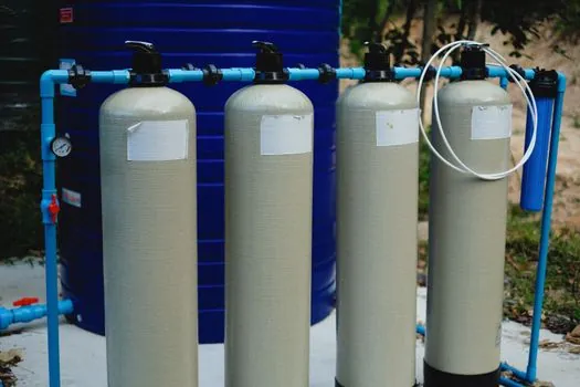
Multistage centrifugal pumps can only carry their own internal hydraulic loads; the suction and discharge piping must have independent supports so weight, thermal expansion, and water hammer do not transfer into the casing nozzles [S1]. Pipe strain on a flanged nozzle is the most common cause of casing-to-frame cracks on sectional multistage builds.
Suction-side rules are stricter than discharge-side: short, straight, air-free, with no high spots that can trap vapour, and the suction pipe diameter stepped up, not down, toward the pump to keep velocity below roughly 2 m/s and protect NPSH. The MD/DG/D frame family uses an internal or external sealing-water take-off at the stuffing box, with mechanical seal as the alternative for the D, DG, MD, DF, and DY types, and that sealing line must be piped and valved before the pump is run up [S3]. On the discharge side, a check valve and an isolating gate valve sit close to the nozzle so reverse rotation on shutdown cannot back-drive the motor, an important protection on high-head DYP and API 610 BB4 builds where a 1,500 to 2,500 m reverse water column can wreck a non-locking coupling [S4][S5].
Mechanical Seal, Bearings, and Lubrication Setup
Shaft seal choice is set at install time, not in the commissioning phase: MD, DG, DF, and DY types accept either packing or mechanical seal, with sealing water sourced from pump discharge or an external service line and fed into the stuffing box at a pressure 0.1 to 0.3 MPa above suction [S3]. The DYP oil pump variant is built for media below 80°C and below 120 cSt, so a hot-oil start before the seal flush is open will coke the seal face within minutes [S4].
Bearing lubrication depends on frame size: the 85-67, 155-67, and 600-60 MD series use oil-bath sleeve bearings, with rolling-element bearings available as an option on the 85-67 and 155-67, while every other MD frame uses grease-lubricated rolling bearings [S3]. On API 610 BB4 units, the heavy-duty rolling bearing assembly is grease-lubricated by default with an optional oil-mist or flooded-sump kit, and bearing housing oil level must sit at the centre of the sight glass on a level base, not against the upper mark [S5]. Dry-running the pump at any commissioning stage destroys the mechanical seal in under a minute, so the seal flush must be verified open before the first motor bump.
Driver Coupling, Rotation Check, and Pre-Start Verification

Direction of rotation is fixed by build: clockwise viewed from the prime-mover side for the D, MD, DF, and DY families, and the same convention holds for the DYP and API 610 BB4 horizontal multistage builds [S3][S4][S5]. A 5 to 10 second dry bump is mandatory before connecting coupling halves, because a three-phase motor wired in reverse on a single-stage unit only loses performance, but on a 13-stage BB4 it can leave the rotor hydraulically locked and stall the drive.
Pre-start checklist: anchor bolts torqued and re-checked after grout cure, alignment re-measured across both coupling faces, mechanical-seal flush open and pressurised, bearing housings filled to the correct level, suction valve open, discharge valve cracked for first run, and a hand on the coupling guard to feel for rubs. The guards stay on; a coupled multistage pump with the guard removed is an immediate lockout event. For a deeper look at how coupling choice and pump type lock together, see this plunger pump spec-gate guide for the broader positive-displacement comparison.
Acceptance Criteria and When to Stop the Commissioning
Acceptance on a multistage install is not a paper sign-off; it is measured. After 30 minutes of dead-headed run, vibration velocity should sit below 4.5 mm/s RMS on rigid foundations and below 7.1 mm/s on flexible bases per ISO 10816-3 Class 1 limits, bearing-housing temperature rise should be under 55 K above ambient with no more than 95°C absolute, and mechanical-seal leakage should be below 3 mL/h on a balanced seal plan. If any of these numbers trips, stop, re-check alignment, then re-check grout. [S2]
On the hydraulic side, the duty point must be reached within plus or minus 8% of the design flow and head before handover, and the seal-flush differential pressure must hold within 0.05 MPa of setpoint. If the unit will not meet these numbers, the fault is almost always piping strain, a starved suction from an undersized line, or a frame that has twisted off-level since grout cured, all of which are install-side defects, not pump defects. A pragmatic reference for the surrounding equipment choices during install planning is the sand blasting machine selection for pump and valve production guide, which covers surface-prep work that often runs in parallel with pump install on a process skid. For the broader pump-class context, including how multistage units sit next to single-stage end-suction and split-case frames, the multistage pump encyclopedia entry gives a useful spec comparison, and the centrifugal pump reference covers the hydraulic principles the install must respect.
Track two signals after handover: vibration trend at the drive-end bearing housing over the first 500 hours, and seal-flush temperature, which should stabilise within 5°C of running-fluid temperature. Either drifting upward is the early warning that alignment, grout, or piping strain is back-loading the pump, and it must be caught before the balance disc or mechanical seal pays the price.
Spec-level background on the components involved: linear guide.