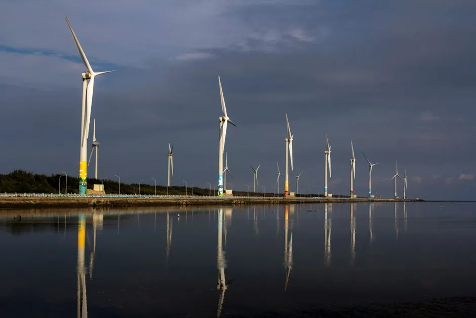
Offshore wind foundation manufacturing equipment in 2026 serves a market heading toward 205 GW of installed capacity by 2030, up from 35 GW at the end of 2020 [S2]. Each GW of fixed-bottom offshore wind embeds roughly 80–110 monopile or jacket foundations, which is why the factory floor, not the turbine, now sets the project schedule [S2][S5].
Three foundation families dominate the equipment pipeline: monopiles for water depths up to roughly 40 m, jackets for transitional depths of 40–60 m, and floating semisubmersibles or spars for sites beyond 60 m [S1][S2]. The equipment that builds them overlaps heavily with shipyard and offshore oil-and-gas platework, but tolerances, weld inspection density, and serial production cadence are stricter [S5][S7].
Foundation types and the equipment each one forces on the plant
Monopiles are single rolled steel cylinders, typically 8–12 m in diameter, 70–100 m long, and 800–1,800 t in finished weight, and they are produced on heavy plate-rolling, longitudinal and circumferential welding, and internal bulkhead fit-up stations [S2][S5]. Empire Engineering notes that jackets, a four-legged lattice structure, are preferred where turbine loads grow with rotor diameter, because the lateral stiffness of a jacket scales with leg geometry rather than diameter [S2].
Floating foundations (semisubmersibles, spars, tension-leg platforms) shift the manufacturing problem from a single thick plate to a buoyant pontoon-and-column assembly with mooring chain or tendon interfaces, which is why ABS published a dedicated design and build guide covering the floating support structure, stationkeeping system, and onboard machinery separate from the turbine [S4]. For project planners weighing fixed vs floating equipment capex, the foundation vehicle encyclopedia entry maps the structural and load-path differences that drive that choice.
Core equipment list inside a monopile or jacket fabrication hall
A modern monopile line stacks these stations: heavy plate receiving and shot-blast, longitudinal seam welding (SAW or tandem GMAW), plate rolling to 8–12 m diameter, circumferential girth welding, flange or transition-piece fit-up, internal platform and J-tube installation, and final NDT [S5][S7]. A jacket cell adds node fabrication (cast or welded Y-, K-, and X-joints), tubular leg rolling, and three-dimensional frame fit-up, all of which depend on large gantry welders and multi-axis positioners [S2].
For monopiles, the bottleneck stations are plate rolling beyond 10 m width and tandem girth welding on walls of 60–130 mm, both of which require purpose-built 200–600 t cranes and weld-positioning heads [S5]. Floating foundation halls instead prioritize large block assembly and outfitted pontoons, which is closer to shipbuilding block-jack logic than to wind-specific work [S4][S7].
NDT, dimensional control, and welding inspection density
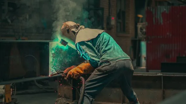
Offshore wind welds are inspected to a higher density than most onshore pressure equipment because fatigue, not burst, governs the design life, with 100% volumetric NDT on main seams common on monopile and jacket contracts [S1][S5]. The dominant methods are ultrasonic phased-array for thick plate seams, magnetic particle or eddy current for fillet welds on secondary joints, and visual inspection against ISO 12944 coating and weld profile criteria [S1].
Operators that come from the additive manufacturing material world should be cautious here: NDT on a 100 mm monopile wall is a different problem than NDT on a printed metal part, and the equipment (UT scanners, TOFD crawlers, phased-array cabinets) is not interchangeable. A practical spec-first primer on the gear itself is in the NDT equipment encyclopedia entry, which covers transducer selection, scanner mechanics, and calibration blocks typical for offshore steelwork.
Coating, anode fit-out, and anti-static handling
Every monopile and jacket is coated in the splash zone, and many floating hulls carry cathodic-protection anodes fitted during assembly, which adds a dedicated coating hall and a controlled-environment blasting and spraying line to the equipment list [S1][S5]. Wind blades and GRP nacelle covers create a separate electrostatic-discharge risk on the shop floor, especially in dry winter conditions, so the same facility typically installs grounding straps, conductive flooring, and humidity-controlled lay-up rooms [S1].
Specifying anti-static equipment for a foundation plant is closer to oil-and-gas hazardous-area practice than to electronics assembly, which is why the spec-first discussion of grounding, ionization, and resistance thresholds in the encyclopedia entry translates directly to wind tower and blade shops. The boundary between anti-static gear and ATEX-rated equipment is not always clean, and a common mistake is to buy one where the other is specified.
Manufacturing throughput, capex, and the serial-production trap
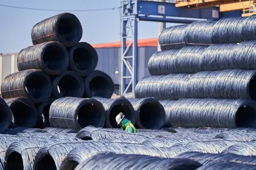
Offshore wind asks for serial production, not one-offs, and a single 1 GW project can require 80–110 monopiles delivered in 24–36 months, which is why a single rolling/welding line is rarely enough [S2][S5]. Throughput is constrained by girth-weld cooling time, NDT chamber capacity, and quay-side load-out, not by the number of welders on payroll, so adding a second shift yields diminishing returns beyond a certain point [S2].
The biggest capex line items are the plate rolling mill, the tandem SAW or GMAW girth-weld cell, the 200–600 t indoor cranes, and the coating hall, with the floating-equipment variant dominated instead by block assembly gantries and outfitting quays [S5][S7]. For buyers comparing fixed and floating capital programs against a 12–20 MW turbine generation, the article on machine vision as the data layer for production capacity planning is a useful complement, since vision-based weld inspection is increasingly how plants protect cycle time without adding headcount.
Selection criteria: who this equipment is for, and who should not buy
This equipment is for shipyards, heavy steel fabricators, and oil-and-gas module builders with an existing plate-rolling and large-crane footprint, ideally within 200 km of a deep-water quay, because transporting a 100 m monopile over land is impractical [S5][S7]. It is not for general steel service centers, light-structural fabricators, or greenfield sites that have not yet secured a multi-year offtake, because the working capital tied up in raw plate alone runs into hundreds of millions of euros for a single 1 GW project [S2][S5].
A practical go/no-go checklist before committing capex: (1) a confirmed 2–3 GW order book from a developer or tier-1 OEM, (2) quay depth of at least 10 m at low water, (3) grid or generator capacity to run tandem-arc welding at full duty, and (4) NDT throughput that does not become the line's pacing station [S5]. Plants missing more than one of these typically deliver the first 10–20 units on time, then miss the back half of the contract.
Standards, codes, and the sourcing signals that matter next

Foundations are designed against DNV-ST-0126, API 2U for offshore platforms, and project-specific IEC 61400 series requirements for the tower-turbine interface, while NDT acceptance generally references ISO 9712 operator qualification and ISO 17640 for ultrasonic techniques [S1][S5]. ABS's floating wind guide (2026) sits alongside DNV's floating design standards, and the two are the dominant reference set for semisubmersible and spar hulls today [S4].
Trackable signals into 2027: ABS and DNV publication updates on 18–20 MW fixed-bottom jackets, the first commercial order book for floating semisubmersible serial production lines, and the EU and US port-readiness programmes for handling 12 m+ diameter monopiles [S4][S5]. For a complementary spec-first read on shop-floor measurement and traceability tooling, see the Sourcing Measuring Instruments from China: 2026 Buyer's Spec-First Playbook, which covers the caliper, laser scanner, and CMM categories that a wind foundation QA plan actually consumes.