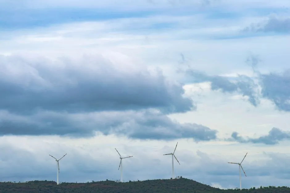
Modern serial production of utility-scale wind turbine gearboxes is sized to a 3-stage architecture with a first-stage planetary section carrying five planets, validated by optical-fiber strain sensing on full-load back-to-back test benches [S3].
The reference unit examined in published structural studies is a Siemens Gamesa Renewable Energy 6 MW gearbox built by Gamesa Energy Transmission, with rotor diameters in the 155-170 m onshore range and offshore targets near 236 m at 15 MW [S3]. For a process engineer laying out a new gearbox line, the dominant design variables are torque density, planet count per stage, and the validation loop that closes FEM models against strain data captured on every shipped unit.
Drivetrain Configuration: Geared vs Direct-Drive Sizing
Geared drivetrains dominate land-based or onshore wind energy, with an estimated 75 percent of turbines having a gearbox, while offshore sites have a more significant share of direct-drive machines, though Vestas and Ming Yang also use geared drivetrains targeting rotor diameters as large as 236 m with expected rated powers of 15 MW. A common geared ratio sits near 90:1, stepping rotor input at roughly 16.7 rpm up to generator speed near 1,500 rpm, while hybrid drivetrains collapse the ratio to around 30:1 by dropping the high-speed stage [S5].
Direct-drive designs eliminate the gearbox entirely and force the generator to spin at rotor speed, which raises generator mass and cost but removes a major mechanical-failure surface [S2]. The trade-off drives a clear line-layout decision: a geared line must host housing machining, gear cutting, heat treatment, assembly, and a load test bench capable of full back-to-back mechanical loading, whereas a direct-drive line shifts floor area toward large-diameter stator winding and magnet handling [S7].
Torque Density and First-Stage Planetary Geometry
Input rotor torque scales with the cubic power of rotor radius, so the step from a 130 m to a 170 m rotor increases gearbox input torque by roughly a factor of 2.2 even at the same tip-speed limit [S3]. Modern units answer that load growth with torque densities of about 200 Nm/kg, achieved through multi-stage planetary architectures with more planets per stage, tighter manufacturing tolerances, and improved surface finishing [S3].
The first planetary stage of a 6 MW gearbox is typically built as a five-planet carrier inside a torque-arm housing, with a stationary ring gear transmitting torque through the planet wheels to a sun pinion that drives the next helical stage [S1][S3]. FEM structural models for this subassembly must capture the rotor-side housing, the first-stage ring gear, and the transition housing between ring gears, all of which are meshed and bolted together in a way that constrains how the molding line for the housings must be tooled for fixturing repeatability.
End-of-Line Test Bench Architecture and Fiber-Optic Validation
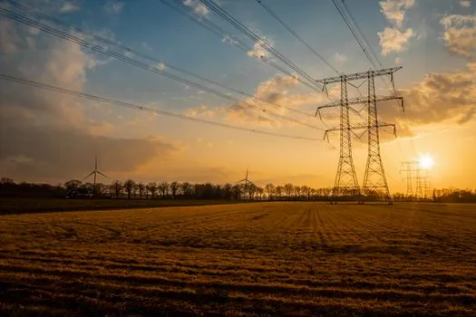
Serial production EOL test benches now use fiber Bragg grating strain sensors on the outer surface of the ring gear, chosen over conventional foil gauges because the optical sensors offer higher signal-to-noise ratio, electromagnetic immunity, and the ability to multiplex several sensing points along a single fiber [S1][S3]. The bench is a full-load back-to-back rig where two gearboxes drive each other so that mechanical power circulates without electrical loading, allowing the unit under test to see 100% rated torque at rated speed [S1].
On the OEM side, ZF Wind Power operates a 30 MW test rig at its Test and Prototype Center, sized to validate complete onshore and offshore powertrains, including the main bearing, gearbox, and generator as an integrated drivetrain [S4]. This integration matters for line design: the EOL test cell must accept a coupled main-bearing/gearbox/generator assembly rather than a bare gearbox, which in turn drives the crane class, foundation mass, and acoustic enclosure specification for that bay of the factory.
Standards, Failure Modes, and Quality-Gate Criteria
Gear and bearing fatigue design follows ISO 6336 for tooth-root bending and subsurface contact fatigue, while wind-specific loading is governed by IEC 61400-4 and AGMA 6006 [S3][S5]. Surface-driven failure modes such as scuffing and micropitting are bounded by ISO 13989-1, ISO 13989-2, and ISO 15144-1, which address lubricant film breakdown, adhesive wear, and surface fatigue from insufficient film thickness [S5].
The most common field failures, however, are not the load cases the standards directly cover: manufacturing errors such as grind temper and material inclusions, scuffing, micropitting, fretting from parked-rotor vibration, ineffective interference fits, and starved internal lubrication paths dominate the failure population [S5]. A serial line therefore has to embed incoming-material inspection, surface-finish verification, interference-fit measurement, and lubrication-passage leak testing as hard quality gates, not as optional checks, because the standards deliberately do not catch these modes on their own.
Line Layout Implications: From Rough Machining to Coupled Test
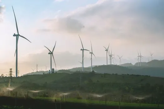
On the shop floor, the sequence runs from rough machining of the torque-arm housing and ring-gear blank, through gear cutting and grinding, through carburizing or nitriding heat treatment, into subassembly of the planetary stage, then the helical stages, and finally into the integrated main-bearing/gearbox/generator bench [S3][S4]. A conveyor sorting line carrying planet wheels, bearings, and ring-gear subassemblies between cells must be designed for the heaviest single lift, which is typically the ring gear plus planet carrier, not the full gearbox.
ZF's SHIFT modular platform has now run for 10 years across onshore and offshore fleets, and the same supplier has shipped more than 10 GW of offshore geared drivetrains with Vestas, which is more than half of Europe's geared offshore installed base [S4]. For a new line builder, the operational signal is that modular, multi-stage planetary architectures with validated EOL strain-sensor test loops are the reference pattern, and any deviation needs a documented basis in IEC 61400-4 load cases plus AGMA 6006 rating margins [S1][S3][S4]. Related reading on sensor retrofit and Industry 4.0 rollout in the same drivetrain context is covered in Wind Turbine Gearbox Industry 4.0 Adoption: Spec, Sensor, and Retrofit Map.
For capacity planning, the next trackable signals are the 15 MW offshore geared platforms now entering type certification, the standardization of fiber-optic strain sensing as a release criterion rather than a development tool, and the migration of main-bearing integration from the nacelle into the gearbox housing, all of which will redraw cell boundaries and crane maps on any greenfield automatic molding line feeding a future gearbox factory.