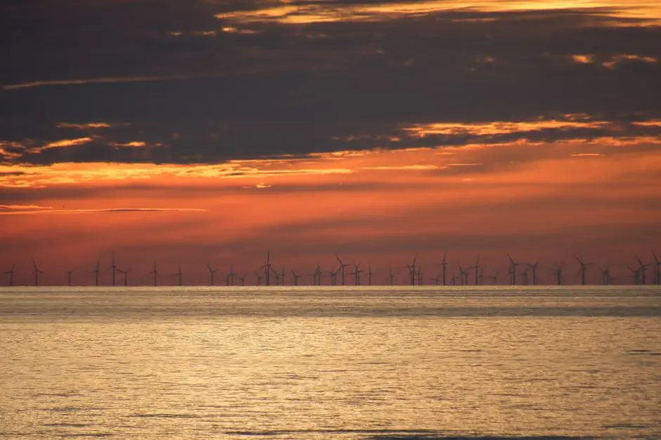
Offshore wind foundation manufacturing is a heavy-plate, thick-wall welding problem before it is a renewables problem, and 2025–2026 factory concepts are being redrawn around pile diameters of 3.5–6 m today, with 8–10 m monopiles and 10–60 m jacket water depths already on the drawing boards [S2].
End-of-2023 global installed offshore wind capacity stood at 75.2 GW, with industry roadmaps targeting 380 GW by 2030 and 2,000 GW of installed capacity on the path to net-zero by 2050, a 25× to 27× expansion that drives the production line throughput question more than any single turbine design [S1][S3]. Foundations and their installation are documented to absorb up to 34% of a wind farm's development budget, so production-line choices dominate LCOE, not blade aerodynamics [S4].
Foundation Types and the Water-Depth Bands That Drive Line Layout
Monopile, gravity-base, tripod, jacket, and floating are the five foundation families in commercial service, and each imposes a different factory footprint [S2]. Monopiles are fixed-bottom structures, dominated by 0–30 m water depths, built around steel pipe piles 3.5–6 m in diameter and 30–40 m long, the configuration used in roughly 75% of installed offshore wind farms [S2][S4]. Tripod and jacket substructures extend the fixed envelope to 20–50 m and 10–60 m respectively, with jacket cited as the most likely mainstream choice for large future turbines because the technology can plausibly reach 100 m water depth [S1][S2]. Floating foundations unlock water depths beyond 50 m using catenary or taut-spread mooring lines with drag or suction anchors, with spar, semi-submersible, and tension-leg platform variants all in service [S3].
Production-line implication: a single-line monopile factory optimized for 6 m diameter cannot economically build 10 m monopiles or 60 m jacket leg nodes, which is why new yards are being designed for modular bays with switching cranage, not single-purpose cells [S6][S7].
Inside a Monopile Cell: Plate Prep, Rolling, Longitudinal Welds, and the Molding Line Bottleneck
A monopile production cell is a four-stage flow: plate receiving and cutting, plate rolling into cans, longitudinal and circumferential submerged-arc welding, and fit-out of the transition piece flange before blasting and coating [S2].
Pile diameter growth changes the dominant process constraint: below 6 m, the limiting step is single-wire SAW deposition rate on the girth welds; above 8 m, it is plate thickness (typically 80–120 mm for the heaviest cans) and the number of welding heads that can fit inside the can without collision [S1][S4]. Production lines targeting 15–18 MW turbines need to weld cans up to 8–10 m diameter and 100–150 mm wall, which forces tandem-arc or multi-arc SAW heads, tandem cold-wire feed, and real-time ultrasonic phased-array inspection at the welding station, not downstream NDT as a separate island [S4][S7]. A 3D soil-structure interaction model that allows a monopile to be shortened by 5 m can save more than USD 100,000 in steel per pile, so the production line must accept frequent design-driven length changes without re-tooling [S4].
Jacket and Floating Substructure Cells: Node Welding, Tubular Geometry, and Conveyor Sorting Line Logic
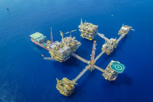
Jacket and floating substructure yards look nothing like monopile lines: the unit of work is a tubular node, not a can, and the canonical product is 4-leg jackets with brace members in the 1–3 m diameter range welded through cast or fabricated node cans [S2][S3]. Production rate is gated by node welding and brace-end preparation, both of which are high-deposition, multi-position tasks where human welders still dominate, although robotic positioners are gaining ground on 2 m and smaller braces [S6][S7].
Floating foundation yards add three more elements: a large-dry-dock or graving dock for spar or semi-submersible hull assembly, a separate mooring-line manufacturing and spooling bay, and anchor handling because each floating unit typically carries 3–9 catenary or taut lines with drag or suction anchors [S3]. Floating concepts are described in the literature as having significant potential for cost reduction and efficiency improvements, but the production line today is closer to offshore-shipyard practice than to monopile serial production, and throughput is still measured in units per quarter, not per week [S1][S3].
Selection Criteria: When a Monopile, Jacket, or Floating Line Earns Its Capex
Foundation choice is governed by water depth, soil, turbine size, and port logistics, and the production line follows the concept, not the other way around [S2][S3]. Monopile lines earn their capex on shallow, sandy or stiff-clay sites in 0–30 m water depth, with serial production of 6–10 m diameter piles; they break down past 50 m because steel tonnage rises non-linearly with both diameter and wall thickness [S2][S4]. Jacket lines are the right answer for 30–60 m depths and large turbines, and are the most credible path to 100 m fixed-bottom water with current design codes [S1]. Floating lines are the only answer beyond roughly 60 m and the right answer for many sites between 50 m and 80 m where fixed-bottom steel tonnage is uneconomic [S1][S3].
Comparison on four decision criteria for factory planners:
1) Throughput. Monopile serial lines: 3–6 foundations per week at mature yards. Jacket lines: 1–2 per week. Floating yards: 1–3 hulls per quarter [S2][S3].<br>2) Steel intensity. Monopile: 600–1,200 t per foundation at 8–10 m diameter. Jacket: 800–1,500 t for water depths above 40 m. Floating semi-submersible: 1,500–3,000 t of steel per unit before mooring [S2][S3].<br>3) Welding hours. Monopile: dominated by girth SAW. Jacket: dominated by node and brace welds. Floating: dominated by hull plate welding plus mooring line termination [S2][S3].<br>4) Yard footprint. Monopile: 300–500 m long linear flow. Jacket: distributed node, assembly, and loadout bays. Floating: graving-dock-dominant [S3][S6].
Geo-Data, Site Conditions, and Why 3D Modelling Reshapes the Line
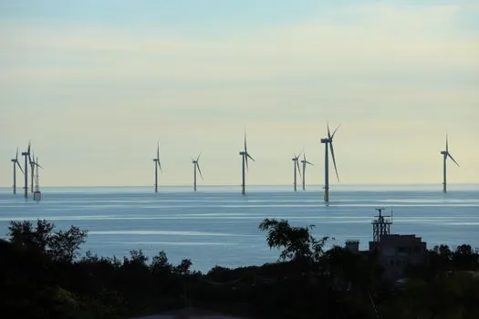
Offshore wind foundation design is unusually sensitive to ground conditions because the loading is cyclic, multidirectional, and applied to a stiff, slender structure, which is why a 3D soil-structure interaction model is now standard for any foundation beyond a simple monopile in sand [S4]. When 1D modelling is replaced by 3D, required foundation dimensions tend to drop, sometimes by 5 m of monopile length, and consultancy-led laboratory testing rather than default test programmes cuts programme time by weeks on a typical 1 GW survey and by months on complex sites [S4].
Sites with deposits susceptible to cyclic degradation, lateral spreading, or seismicity push the design toward 3D digital twins that include the soil volume, not just the structure, and that level of modelling feeds back into the factory via more accurate fatigue spectra on the welds, not via different steel grades [S4].
Logistics, Loadout, and the Foundation Vehicle Question
A foundation production line is not finished at the paint bay; it is finished at the loadout quay, and the choice of foundation vehicle for moving 1,000+ t structures determines yard geometry as much as the welding cells do [S2][S6]. Marine transportation and offshore installation are documented as the riskiest construction phases for monopiles, with pile sliding, hammer refusal, and crane damage as the named failure modes, so loadout tolerance, upending frame geometry, and sea-fastening design are part of the production line, not an afterthought [S2].
Self-propelled modular transporters (SPMTs) with 4–6 axle lines per unit, each axle rated 40–60 t, are the standard for moving monopiles and jacket substructures from the assembly bay to the quay; for floating hulls, the graving dock does double duty as the loadout basin, flooded at the end of the build cycle [S3][S6]. The supply-chain bottleneck is no longer the steel; it is the limited number of heavy-lift installation vessels, which means yards are being co-sited with quays deep enough for next-generation jack-ups, and that siting decision is now locked in before the first molding line bay is laid out [S3][S5].
Quality, Standards, and Inspection Footprint
Offshore wind foundation welds are governed by a stack of standards rather than a single code, with EN 1090-2 execution class typically EXC3 or EXC4 for primary structural welds, ISO 3834 quality requirements for fusion welding, and project-specific fatigue spectra derived from the integrated load analysis (ILA) that the Empire Engineering guide treats as a non-negotiable design input [S3][S4]. Non-destructive testing usually combines phased-array ultrasonic testing (PAUT) for the thick can walls, radiographic testing for the tubular T-joints on jackets, and magnetic particle inspection for the transition piece flange weld roots, with 100% PAUT now common on new monopile lines rather than the 10–20% sampling of older specifications [S4][S7].
The production line should treat inspection as in-line rather than downstream: every welding station needs at least one NDT-qualified operator on shift, and the data should feed a digital weld map per foundation, not a paper traveller, because traceability is what auditors look for first when a fatigue crack shows up in service [S4]. Coatings and cathodic protection are specified in the same digital thread, with typical shop-applied epoxy glass-flake systems in the 600–1,200 µm DFT range plus sacrificial aluminium anodes for the splash and submerged zones, although the exact call-out is project-specific and not invented here [S6][S7].
Limitations, Failure Modes, and the Real Risk Register
The literature is explicit on what fails first: for monopiles, pile sliding (the pile sinks uncontrollably on entering soft strata), hammer refusal (the pile cannot be driven to target depth), and crane damage during upending are the named construction-period risks; for jackets, the equivalent risks are pile-through-leg tolerance and node-can cracking during fatigue cycling [S2]. Floating systems add mooring-line failure, water-ingress in buoyancy tanks, and station-keeping loss, and these are not factory risks but design risks that the production line can only mitigate by welding the chain terminations under full traceability [S2][S3].
Two constraints are not negotiable: first, the applicable depth of fixed foundations is realistically capped near 50 m with current steel intensity, so any yard built only for monopiles will be obsolete within 10–15 years as projects move into the 50–80 m band [S1]. Second, floating has significant potential for cost reduction but is not yet at monopile-level serial-production cost, so a yard that bets only on floating carries a heavier demand-risk premium than a yard that can switch between jacket and floating hulls [S1][S3].
Track the next two signals to see which line design wins: (1) the next commercial-scale floating project order book in Europe and Asia-Pacific, which will decide whether spar, semi-submersible, or TLP hulls become the de-facto floating line template, and (2) the first serial monopile line built for 8–10 m diameter, 100–150 mm wall cans, which will set the throughput benchmark for the late-2020s. For related mechanical spec work on the components that ride on these foundations, the linear module selection map for wind power pitch, yaw, and brake duty covers the actuator side of the same turbine.