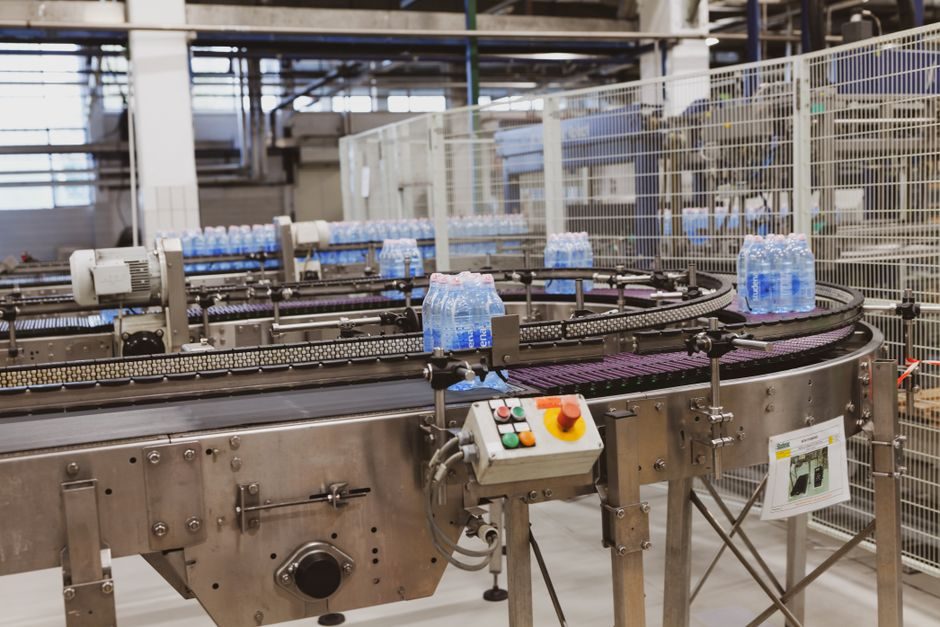
Machine vision systems are purpose-built combinations of imaging hardware, optics, illumination, processing silicon and recognition software, deployed on factory floors to control quality, throughput and process deviation in real time [S3]. Allied Market Research values the segment at $29.7 billion in 2019, with a forecast of $74.9 billion by 2027 at an 11.3% CAGR from 2020 to 2027 [S1].
The end-use mix is industrial, automotive, electronics, healthcare and aerospace & defense, with healthcare forecast as the fastest-growing vertical at 15.3% CAGR on the back of clinical diagnostics, in-vitro diagnostics and surgical lab automation spend [S1]. U.S., Japan, South Korea and Germany anchor automotive demand; the U.S. is identified as the fastest adopter for consumer electronics and EV/ADAS-adjacent inspection [S1].
What a Machine Vision System Actually Is (and What It Is Not)
A machine vision system is a hardware-plus-software stack based on object or pattern recognition, distinct from general-purpose industrial cameras or barcode readers alone [S3]. On a typical block diagram the function blocks include object illumination, image sensor + lens, high-speed interface memory, NOR flash, point-of-load and switching regulators, USB 3.2 peripheral controllers, low-capacitance ESD protection, wired/wireless connectivity and an AI-enabled processor running the recognition algorithm [S3].
It is NOT a closed-circuit security camera, a microscope, or a simple photo-electric sensor: the value of an MV system sits in the deterministic, traceable inspection decision it returns to a PLC or robot controller on a production line, with yield data logged per unit [S3]. Integrators such as Fisher Smith frame their offering as a turnkey service from illumination and optics specification through to complete line-side delivery, with systems interfaced to a wide range of automation and robotic equipment [S2].
Manufacturing-Process Map: From Component Lot to Calibrated Station
An MV system is an assembly, not a fabrication: the manufacturing process is dominated by sub-assembly, calibration and software burn-in rather than wafer or mechanical stock production. The typical process flow, as observed across the component stack, runs: incoming optical and electronic component inspection → printed-circuit-board assembly of the vision controller and interface boards → sensor/optics sub-assembly in a clean bench → firmware and AI model load → optical alignment and focus calibration against a certified target → environmental stress screening → final acceptance test on a customer-representative line [S2][S3].
Image acquisition requires high-performance processors, adequate data communication, and sufficient memory; recognition depends on intelligent algorithms detecting irregularities in the manufacturing process [S3]. For a deeper view of how vision controllers slot into a wider line, the machine vision system reference covers component categories in detail, while the vision controller entry covers the processing-and-IO layer that turns pixels into PLC-level decisions. Infineon's reference design uses EZ-USB FX3 USB 5 Gbps peripheral controllers, HyperRAM-class low-pin-count expansion memory, PSRAM, and Flash+RAM MCPs in this controller role [S3].
Selection Criteria: Matching Architecture to Inspection Task
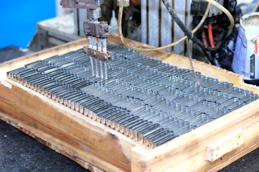
Three decisions drive the BOM before any software work begins: camera technology (area-scan vs line-scan vs 3D/ToF), processing topology (smart camera with embedded inference vs PC-based frame grabber + GPU vs FPGA/ASIC), and illumination (LED ring, bar, coaxial, dome, structured-light projector) [S2][S3]. Line-scan is favored for continuous-web inspection (foil, paper, printing, battery separator) where the part moves under a stationary camera; area-scan dominates discrete-part inspection (electronics, machined components); 3D/ToF is used for bin-picking, weld seam profiling and PCB height mapping [S2].
For high-speed interfaces, USB3 Vision, GigE Vision, CoaXPress and Camera Link HS remain the dominant transport layers; 10 GigE and CoaXPress 2.0 are the practical ceiling for high-resolution, multi-camera cells. The lighting decision is often more determinant of pass/fail rate than the camera itself: specular or low-contrast parts typically need coaxial or dome lights, while transparent films need backlight or polarized illumination [S2]. For metrology-grade cells, the vision measuring machine entry covers the optical metrology subset, which overlaps with multi-point calipers and contact probes on the same workpiece.
Who It's For vs Who Should Avoid It
MV systems fit high-volume, high-mix discrete manufacturing (automotive body-in-white, electronics SMT, pharma fill-finish, food sorting), continuous-web lines (battery separator, film, nonwoven), and regulated environments where 100% inspection is mandated rather than sampled [S1][S3]. A relevant adjacent reference is our battery separator manufacturing walkthrough, where inline machine vision catches pinholes, coating streaks and caliper deviation that downstream winding cannot tolerate. They are also the enabling inspection layer for the TOPCon cell process flow, where cell color and EL imaging feed sorting decisions.
MV is the wrong tool where the defect signature is below the optical resolution of the sensor and the lighting cannot resolve it, where the part-to-part variability is so high that a fixed algorithm cannot generalize, and where the cycle time required is below the camera + processing latency budget. For sub-millisecond decisions in stamping or welding, eddy-current, laser triangulation or acoustic emission sensors remain the better fit. For sub-100% inspection of low-value assemblies, the cost-of-ownership math on a full MV cell rarely closes.
Component Stack Comparison by Decision Criterion
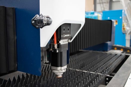
Four practical options line up against four decision criteria (latency, integration effort, unit cost, AI/ML headroom): smart cameras (low latency, lowest integration effort, mid unit cost, limited AI headroom), PC-based frame-grabber + GPU (highest latency budget flexibility, highest integration effort, mid-to-high unit cost, strongest AI headroom), FPGA/ASIC vision controllers (lowest deterministic latency, mid integration effort, high unit cost, moderate AI headroom via quantized models), and embedded SoC boards (mid latency, low integration effort, low-to-mid unit cost, mid AI headroom) [S2][S3]. Smart cameras win for straightforward presence/absence and barcode reads; PC + GPU wins for complex defect classification with deep learning; FPGA/ASIC wins for in-line 100% inspection at line speeds above 10 m/s; embedded SoC wins for cost-driven retrofit cells.
A simple buy-or-build question often decides the rest: integrators like Fisher Smith explicitly position themselves as bespoke turnkey suppliers from illumination and optics specification through line-side delivery, with custom solutions where off-the-shelf smart cameras do not meet the requirement [S2]. On the silicon side, suppliers such as Infineon package the function as a reference design — image acquisition, high-speed interface memory, low-capacitance ESD protection, switching regulators and USB 3.2 peripheral controllers — with the AI inference model typically loaded as customer or integrator IP on top [S3].
Use Cases: Automotive, Electronics, Healthcare, Logistics
Automotive is the dominant manufacturing vertical: highly automated mass production incorporates machine vision for body-in-white dimensional checks, weld inspection, paint defect detection, and ADAS sub-assembly verification; ON Semiconductor signed a licensing agreement with CEVA to incorporate an imaging and vision signal processing platform in automotive applications [S1]. In electronics and semiconductor back-end, MV handles die placement, AOI of PCBs, and final functional board test imaging. In healthcare, MV underpins clinical diagnostics, in-vitro diagnostics and surgical lab automation, the fastest vertical at 15.3% CAGR [S1]. In logistics, fixed-mount and handheld barcode readers feed sortation, with ANPR/LPR an adjacent but separate MV application [S2].
Limitations, Failure Modes and Sourcing Risks

Three failure modes dominate field returns: (1) illumination drift — LED aging shifts the spectral output and breaks the threshold set at commissioning, (2) lens contamination — oil mist, coolant or dust on the optics creates false defects, (3) algorithm drift — lighting or supplier-part changes invalidate the trained model, requiring periodic re-validation [S2][S3]. Sourcing risk concentrates around image sensors (single-source Sony or onsemi supply), FPGA/AI accelerators (lead times 26-52 weeks in tight cycles), and machine-vision-grade optics (limited Tier 1 suppliers).
Mitigation in 2026 looks like: dual-source sensor qualification, modular optics so swap-in does not require re-alignment, and a documented re-validation procedure on every lighting change. Memory and storage are not usually a bottleneck — Infineon's reference design specifies HyperRAM and PSRAM for frame buffering, with NOR flash for boot and code, and Flash+RAM MCPs where board real estate is tight [S3]. ESD and surge protection on every external connector is standard, with low-capacitance ESD devices specified to protect high-speed image data lines without degrading signal integrity [S3].
Standards, Sourcing and What to Track Next
There is no single global machine-vision standard, but the practical anchor points are: GigE Vision, USB3 Vision, CoaXPress and Camera Link HS for transport; EMVA 1288 for sensor characterization; and IEC 62443 for cyber security on connected cells. Sourcing-side, the next 6 months will be shaped by sensor lead times and the migration of more inference to on-device AI accelerators. Two trackable signals: (1) the cadence of AI accelerator announcements at the SPS / Vision show in late Q4 2026, and (2) any new EMVA 1288 revision work that may impact how sensor signal-to-noise is reported across vendors. [S1]