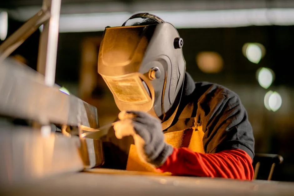
Electrolyzer manufacturing equipment covers the full production chain from bipolar-plate coating and membrane-electrode-assembly (MEA) lamination, through stack pressing and leak testing, to rectifier skid integration, water purification, and gas-conditioning balance of plant (BoP). For green-hydrogen projects, the spec sheet must lock stack technology first, because PEM, alkaline, and solid-oxide (SOEC) cells drive fundamentally different tolerance and cleanroom requirements.
Electrolyzer OEM stack capacity globally is dominated by alkaline and PEM architectures, with SOEC in pre-commercial scale-up; the U.S. Department of Energy has framed a target of $2/kg clean hydrogen by 2026 through electrolyzer cost reduction, lifetime extension, and installation-efficiency gains [S1]. In zinc electrowinning, which shares the same electrochemical-reactor DNA, Chinese plant data shows internal cell lengths from 4030 mm to 10050 mm and cathode areas from 1.13 m² to 3.6 m² per plate as the practical scale envelope for industrial electrolyzers [S3].
Stack Technology Selection Drives Every Downright Equipment Decision
Alkaline electrolyzers operate with liquid KOH electrolyte and use porous nickel-coated electrodes, tolerating looser plate-flatness tolerances and ambient-pressure assembly; this keeps the construction machinery and equipment footprint on the cell-assembly line modest. PEM cells run on a solid polymer membrane under 30-80 bar differential, which forces vacuum-assisted MEA hot-pressing, laser-welded titanium bipolar plates, and helium-sniff leak testing below 1x10⁻⁶ mbar·L/s as baseline.
A 220 mm x 110 mm x 25 mm bipolar bench cell on a ruthenium-iridium or platinum-coated titanium substrate, fed with 120-150 L/h of filtered water at 0.1-0.4 MPa and powered at 0-12 V DC, illustrates the small-format end of the spectrum; the same design language scales to the 10050 mm long, 1330 mm wide, 2460 mm deep industrial tank used for zinc electrowinning, with 108 cathodes per tank [S2][S3]. The control window (PH 6.0-9.5, current limit 0-5 A, 45°C max) on the bench unit is the kind of operating envelope that larger stacks inherit with proportionally scaled instrumentation.
Bipolar Plate and Electrode Manufacturing: Coating, Pressing, and QC
Bipolar-plate production is the cost bottleneck. For alkaline and zinc-electrowinning cells, rolled or cast lead-silver, aluminum, or stainless plate is common, with mechanical leveling and a final acid-pickling pass. PEM plates are stamped or photo-chemically-etched titanium or stainless, then PVD-coated with platinum group metals; coating thickness uniformity must be held within ±5% across the active area, otherwise current-density hot spots form and accelerate membrane degradation [S2][S3].
Pressing force on the stack assembly fixture scales with cell count: a 100-cell PEM stack at 250 cm² active area typically needs 50-80 kN of preload on a servo-hydraulic press with ±1% load control and a heated platen at 80-130°C for MEA bonding. After pressing, NDT equipment is deployed for high-voltage insulation checks (typically 500-1500 V DC hipot) and pressure-decay leak testing; specifications at 1.5x design pressure with a 30-minute hold are typical for atmospheric-pressure alkaline cells, while PEM cells need the vacuum-hold or helium-mass-spectrometer approach.
Rectifier, Power Electronics, and Skid Integration
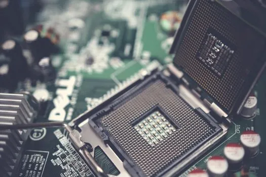
The rectifier is the single largest BoP item by both footprint and capital cost. For stacks up to ~5 MW, IGBT-based thyristor rectifiers with a 12-pulse transformer and ±1% current regulation are standard; above 5 MW, modular parallel IGBT units with active front-end harmonic filtering are common to keep THD below 5% as expected by most utility interconnect rules. Output rating must cover the full dynamic range from 20% partial load (cold-start ramp) to 110% overload, because renewable-coupled stacks cycle frequently [S1].
Stack-frame skids integrate the cell stack, gas-water separators, and instrumentation in a stainless frame; linear slide rails and cross-roller guides are used in automated stripping and stacking stations for repeatable cell-frame alignment to within 0.05 mm. For zinc plants, automated cathode-stripping machines and multifunctional overhead cranes replace manual handling, with 48-114 cathodes per tank cycled on 24-48 hour cycles depending on current density [S3]. The same automation pattern, robotic cathode handling, auto-stripping, and conveyorized sheet washing, is now migrating into hydrogen electrolyzer plants to compress labor cost per stack.
Water Treatment, Drying, and Gas Conditioning BoP
Feed-water quality governs membrane life. PEM requires deionized water with conductivity below 1 μS/cm, TOC under 50 ppb, and silica under 10 ppb; a typical skid integrates reverse osmosis followed by mixed-bed polishing and continuous online conductivity meters. For larger alkaline systems, softened and dechlorinated town water is acceptable, with a KOH dosing loop at 25-30 wt% held in a stainless tank with anti-static equipment bonded and grounded to prevent ignition of the H₂ vent during refill. [S2]
Post-stack gas conditioning is more demanding on the PEM side. H₂ exiting the cathode side is typically 99.8-99.9% pure at 30-80 bar but carries entrained water and oxygen crossover traces; a stainless coalescing filter, twin-tower pressure-swing adsorber, and a catalytic deoxygenation stage are standard before product H₂ enters the buffer tank. Oxygen-side treatment on the anode is simpler, vent through a demister, water knockout, and safe vent stack positioned above roofline per NFPA 2 guidance referenced in U.S. DOE installation materials [S1].
Comparison of Stack Architectures Against Plant Equipment Criteria
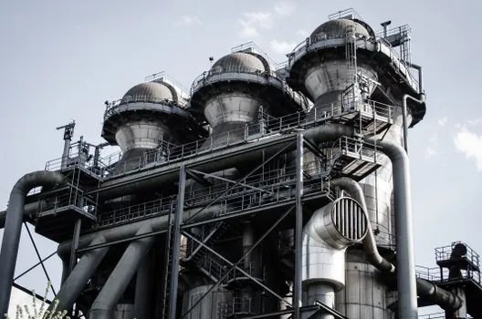
Selecting alkaline versus PEM versus SOEC drives specific equipment-line differences. The matrix below uses four decision criteria that procurement and process engineers typically weight: cathode-pressure tolerance (driving the cell-press tonnage and leak-test equipment), feed-water purity (driving the deionized water skid and the linear guide tolerance on automated dosing skids), assembly-line cleanliness class (driving the cleanroom footprint and crossed-roller guide precision on MEA handlers), and stack operating temperature (driving furnace vs. press choice). [S2]
Alkaline scores lowest on water purity (tolerates softened water, low-cost skid), lowest on cleanroom (ISO 8 or ambient is acceptable), and lowest on temperature (60-90°C, no furnace needed), but its cell-press tonnage is comparable to PEM at the same active area. PEM scores strictest on water purity (DI water mandatory) and tightest on cleanroom (ISO 7 or better) but operates near ambient-90°C. SOEC scores loosest on cleanroom, but worst on water purity for the BOP steam side and highest on temperature (700-850°C), which forces a tube-furnace or roller-hearth kiln on the production line rather than a hydraulic press [S1][S3].
Installation, Commissioning, and Standards Reference Set
Site installation, not the stack itself, is often the larger cost lever. The U.S. DOE summary report flags that reaching $2/kg H₂ requires parallel cost reductions in equipment, lifetime, energy efficiency, low-cost electricity, and system installation, with the EPC and AHJ coordination noted as a recurring schedule risk [S1]. Engineers should anchor specifications to NFPA 2 for hydrogen installations, ISO 22734 for hydrogen generators using water electrolysis, and IEC 61511 for the safety-instrumented functions on the H₂ vent and O₂ vent skids.
For the production line itself, machine-safety compliance is built around ISO 13849-1 on the press and stacking stations and IEC 60204-1 on the rectifier skid electrical package. Plan a 6-9 month FAT-to-SAT window for the rectifier and water skid, and a parallel 4-month window for the plate-coating and MEA lines, then a 2-month integrated commissioning phase with vendor field-service engineers on site for stack torque and leak-test sign-off.
For a related process-engineering view on how the cell-tank geometry and cathode-stripping cycle drive plant throughput, see the zinc-electrowinning equipment case in Green Hydrogen Production Line Design: 2026 Stack, Skid, and BoP Spec Map. For the downstream cost arithmetic, Green hydrogen cost breakdown: 2026 LCOH drivers and parity math maps the same equipment spec sheet onto the LCOH spreadsheet.