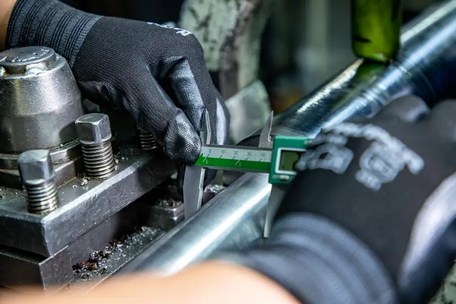
Optical comparators still anchor 2D dimensional inspection in job shops and metrology labs because they overlay a magnified profile against a calibrated screen or template, and the dominant buy decision is the light path, vertical or horizontal, dictated by part geometry [S3].
Directindustry lists 5 manufacturers offering 6 active optical comparator models in its measurement category, a small but stable supplier pool where the buying criteria are well-defined and largely engineering-driven [S1]. Mid-range floor and bench units from the same family routinely cover 14 in to 32 in screen diameters with 5X to 100X lens magnification, and the right combination determines whether the instrument resolves 0.001 mm or only 0.020 mm on a given part [S3].
Light path: horizontal for shafts, vertical for flat parts
A horizontal light path sends the beam across the stage, so long, heavy, or rotationally symmetric parts sit on V-blocks or between centres, the configuration used for transmission shafts, threads, castings and machined components [S3]. A vertical light path sends the beam up through a glass plate on the XY stage, the natural setup for gaskets, O-rings, stampings, and PCB features, and it is the only practical geometry when both X and Y measurements are made with the part simply resting on the table [S3].
Vertical machines typically have quick-release mechanisms on both X and Y axes, while horizontal machines usually only offer quick release on one axis, which makes vertical layouts measurably faster for short, repetitive 2D measurement routines [S3]. For buyers comparing the two, the rule is simple: if the part can stand on its own footprint and is shorter than the stage travel, go vertical; if it has to be supported externally or rotated, go horizontal.
Screen size and stage capacity
Screen diameters in current production runs span 14 in to 32 in, but the right size is set by how much of the part must be visible at one time, not by raw diameter [S3]. A quick sizing method is to divide the screen diameter by the lens magnification: a 10X lens on a 16 in screen shows 1.6 in of part, and best practice is to keep the image at least 1 in inside the screen margin when an overlay is in use [S3].
Stage capacity scales with screen size. Benchtop units of 16 in screen and below typically handle parts up to 150 lb, which covers most stamped, turned and small-machined components, while larger floor units are needed for castings, forging flash, and long shaft work where both travel and rigidity become limiting [S3]. A buyer who skips the stage and travel check ends up with a comparator that can see the feature but cannot bring it under the lens.
Lens magnification and what it really resolves
An attentive operator can repeatedly discriminate about 0.004 in (0.10 mm) on the comparator screen, and dividing that figure by the lens magnification sets the usable resolution of the system [S3]. The published table maps this directly: 5X resolves 0.0008 in (0.020 mm), 10X 0.0004 in (0.010 mm), 20X 0.0002 in (0.005 mm), 25X 0.00016 in (0.004 mm), 31.25X 0.0001 in (0.003 mm), 50X 0.00008 in (0.002 mm), 62.5X 0.00006 in (0.0016 mm), and 100X 0.00004 in (0.001 mm) [S3].
Higher magnification is not free: the field of view shrinks proportionally, so a 100X lens on a 16 in screen shows only 0.16 in of part at a time, which is workable for an edge or radius but impractical for an outline. The lens stack also has to match the screen diameter, otherwise magnification and field of view fight each other and the part has to be repositioned constantly [S3].
Readout tier: overlay, XY DRO, or CNC with edge detection
For pass/fail checks against a fixed template, a base comparator without scales and a printed overlay is the cost-effective choice, and the overlay image should still be kept at least 1 in inside the screen margin to limit parallax error [S3]. When positions and distances must be recorded, an XY digital readout covers most needs, while circles, angles, and parametric distances need a geometric-capable readout or M2-style software package [S3].
Repetitive part runs justify a CNC-capable readout, and adding automatic edge sensing removes operator subjectivity and tightens repeatability, which is often where the published accuracy spec stops being theoretical and starts being real [S3]. Used Mitutoyo PH-A14-class horizontal comparators with QM-Data 200 still trade on the secondary market with calibration certificates, illustrating that the readout, not just the optics, drives residual value [S6].
Tooling, fixturing, and where comparators stop being the right tool
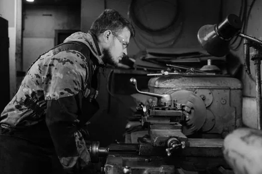
Standard tooling packages, V-blocks, centres, rotary stages, and overlay holders, are usually quoted alongside the comparator, and the right tooling can shift effective accuracy more than a lens upgrade, because a part held between centres reads very differently from a part floating on a glass plate [S3]. Buyers should spec the tooling list at the same time as the machine, not as an afterthought, otherwise a CNC stage with 0.001 mm resolution is wasted on a part that flexes under its own weight.
Optical comparators are 2D, non-contact, and limited to profile and edge geometry, so they are not the right instrument for true 3D surfaces, internal features hidden by other geometry, or sub-micron surface finish. When the duty is dimensional rather than geometric, modern alternatives such as a portable laser tracker are more appropriate, and the practical selection logic for those devices is laid out in this portable laser tracker spec map. For process-tank level work, where many engineers first encounter "optical" sensors, the spec-first routing for radar vs ultrasonic level meters is a parallel case study in choosing by physical principle before brand. And buyers who need a deeper refresher on what a comparator actually projects can consult the optical comparator reference page before locking the lens stack.
Shortlist logic: 4 paths through the decision
Path 1, benchtop vertical, 14 in or 16 in screen, 10X and 20X lenses, overlay only: fits gaskets, stampings, small turned parts under 150 lb, and usually lands at the bottom of the price band [S3]. Path 2, floor vertical, 20–24 in screen, XY DRO with geometry package, plus V-block set: fits electronics, plastic mouldings, and small precision stampings where X, Y, diameter, and angle are all measured [S3].
Path 3, floor horizontal, 24–32 in screen, between-centres workholding, CNC readout with auto edge detection: fits shafts, threads, and long machined components where the part has to be supported on its axis and rotated under the beam [S3]. Path 4, refurbished PH-A14-class horizontal with QM-Data 200 and current calibration: fits buyers who need Mitutoyo optics and a recognised model code but at secondary-market price points, with calibration dates that must be checked before acceptance [S6].
The decision matrix stays the same across all four: light path from part geometry, screen size from field of view, lens from tolerance, stage capacity from part weight, and readout tier from measurement complexity, with tooling and calibration as the two variables that decide whether the published accuracy actually shows up on the shop floor [S2][S3].
Two trackable signals for the next buying cycle: monitor whether suppliers expand CNC and edge-sensing options on 14 in and 16 in benchtop verticals, since that combination is currently the bottleneck between Path 1 and Path 2; and watch secondary-market listings of Mitutoyo PH-A14-class units with valid calibration for evidence of price floors in the horizontal segment [S1][S6].
Spec-level background on the components involved: optical glass, and pressure transmitter.