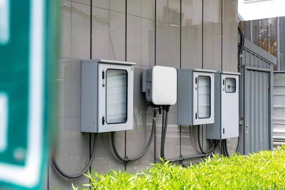
OSSD1 and OSSD2 are two cross-monitored, out-of-phase 24 V DC pulsed outputs on every Type 4 light curtain receiver; the safety function lives or dies on how those two wires terminate, so a dedicated safety relay or a SIL/PL-rated input module on a safety PLC is the only correct destination [S2][S4].
The receiver also needs 24 V DC power, EDM feedback from the contactors, and a reset input for manual restart. Most modern light curtains, including Leuze MLC 500 and ELC 100 families, use optical synchronization between Tx and Rx, so no separate sync cable is required [S2].
OSSD Signal Behaviour You Must Understand Before Wiring
OSSD is a physical-layer safety protocol, not a generic discrete output: each of the two wires carries a pulsed signal roughly 100 µs wide, the pulses are deliberately out of phase, and the test period is short enough that a stuck-high, stuck-low, short-to-24 V, short-to-0 V, or cross-shorted pair is detected as a fault [S4]. Loss of either pulse, or any anomaly in pulse timing, forces both outputs OFF and the machine into a stop state, which is why a scope on OSSD1 versus OSSD2 looks like two interleaved square-wave heartbeats when the curtain is clear [S4].
Because the protocol is defined by pulse timing and cross-check, OSSD outputs are not galvanically isolated like relay contacts; the light curtain, the safety relay, and the PLC input module must share a common 24 V DC reference, and a single OSSD wire cannot be paralleled to two different loads, since loading changes the pulse edges seen by the monitor [S4].
Step 1: Decide NPN vs PNP Against the Safety Input
PNP sourcing is the default for every new light curtain wiring in 2026, because modern safety relays and GuardLogix / SIMATIC F-CPU safety modules all source-current on the input side; NPN sinking survives only in legacy Japanese or older PLC installations [S2]. A PNP OSSD switches its load to +24 V when the beam is clear, so the safety input sees a logic-high for "safe", which is the convention every SIL-rated input module is designed around [S2].
Mismatching NPN output to PNP input, or vice versa, gives the appearance of a dead channel: the input never sees the expected edge, no fault is declared, and the system either refuses to start or, worse, ignores a real stop request; datasheet verification of output type on the light curtain AND input type on the safety module is the only safe way to start [S2].
Step 2: Wire OSSD1 and OSSD2 to a Safety Relay or Safety PLC
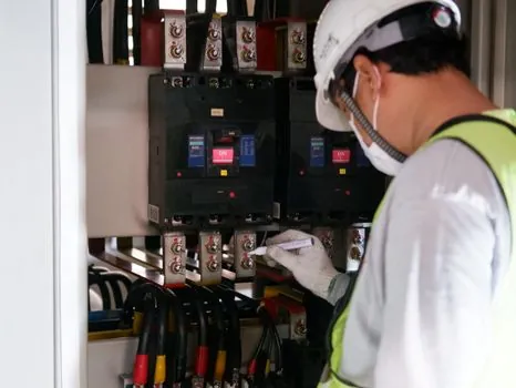
The wiring topology is fixed: OSSD1 to safety input channel 1, OSSD2 to safety input channel 2, 24 V DC to the receiver power terminals, 0 V return shared with the safety module, EDM contactor feedback loop wired into the safety relay's EDM terminal, and a manual-reset pushbutton wired to the reset terminal if the application requires monitored manual restart [S2][S6].
For a standalone safety relay such as the AutomationDirect OSSD / light curtain series, the two OSSD wires land on dedicated S11/S12 or equivalent inputs and the relay's safe outputs (typically 13/14, 23/24, or 33/34) drop out the contactor coil on any fault [S1][S2]. For an Allen-Bradley GuardLogix 5380 or a Siemens F-CPU, the two OSSDs map to a paired safety input tag (for example, SI0/OSSD_Input.In0 and In1), and the controller's safety task does the cross-check in software, which is why the application program must explicitly read both channels as a paired, discrepancy-monitored tag, not as two unrelated booleans [S6].
The most common field error is wiring only one OSSD, or merging both into a single input, which defeats the dual-channel cross-monitoring and reduces the system from PL e / SIL 3 down to a single-point-of-failure design that cannot pass a risk-assessment audit [S2].
Step 3: EDM, Reset, and Response-Time Budget
EDM (External Device Monitoring) is the feedback loop from the contactors back into the safety relay: normally-closed auxiliaries on each contactor are wired in series into the EDM terminal, so the relay confirms the contactors actually dropped out within a few milliseconds of the OSSDs going OFF, and a welded contactor is detected as a fault on the next cycle [S1][S2].
Reset mode selection matters for compliance: automatic reset is only legal for guarded machines where a person cannot reach the hazard with the curtain blocked, while manual monitored reset is mandatory for most press, robotic, and material-handling applications and requires a spring-return pushbutton that closes to +24 V only while held, with the relay validating the 0→1→0 edge before re-energising the outputs [S2]. Total safety-stop response time, curtain response plus safety relay plus contactor drop-out, must be shorter than the machine's calculated stop time, which is why OSSD and safety-relay response times in the 8-30 ms range are typical and must be summed on the safety function calculation sheet [S1].
What You Must NOT Wire the OSSD Outputs To

OSSD outputs are never wired to a standard 24 V DC digital input on a non-safety PLC for the safety stop function, because a standard input has no cross-check, no discrepancy timer, and no EDM validation; a shorted OSSD to 24 V will read as a permanent logic-high and the PLC will think the curtain is clear even with a broken beam [S4][S5].
Auxiliary (non-OSSD) outputs on the receiver exist for exactly this case: a single solid-state or relay auxiliary can be wired to a standard PLC input for status, mute sequencing, or HMI indication, while the OSSDs go to the safety module; the auxiliary output does not participate in the safety function and is allowed to fail without stopping the machine [S2][S8]. For cascade setups with multiple curtains on one safety zone, the field guide on Safety Light Curtain Cascade Wiring for Multi-Zone Protection covers how the OSSD pairs chain through a single safety relay.
2026 Field-Commissioning Checklist
Before energising, confirm: OSSD output type is PNP, both OSSDs are landed on paired safety inputs, 24 V / 0 V reference is common with the safety module, EDM loop is wired in series from the contactor auxiliaries, and reset wiring matches the documented mode (auto or monitored manual) [S2][S6].
During commissioning, force a beam break at the closest, mid, and farthest points of the protected field; both OSSD LEDs on the receiver must turn OFF within the datasheet response time, the safety relay must drop out, and the contactor auxiliaries must feed back an open state on EDM. Re-test weekly with a certified test rod sized to the detection resolution declared on the curtain's nameplate, and log the test on the machine's safety inspection record per ISO 13849-1 verification intervals [S2].
Options Compared: Where the OSSD Pair Should Land
Three wiring destinations are common in 2026, and the choice is driven by SIL/PL target, panel space, and integration cost. [S2]
A dedicated OSSD / light-curtain safety relay (AutomationDirect, SICK UE10, Pilz PNOZ s5) is the lowest-cost option for a single curtain on a single hazard, with response times typically in the 10-20 ms range and onboard EDM plus reset wiring built in [S1]. A modular safety-PLC input slice on a GuardLogix, SIMATIC F-CPU, or Allen-Bradley POINT Guard I/O is the right answer for multi-guard systems, muting, and where the safety logic shares variables with the standard PLC over a single backplane. A wireless OSSD bridge is the third option, used only where cable runs are impractical, with paired SICK or Banner safety radios providing the same dual-channel cross-check over a 2.4 GHz link; cost is roughly 4-8x a wired relay and is reserved for retrofit or conveyor-spanning applications.
Track the SICK deTec4, Banner SX5, Keyence GL-R, and Leuze MLC 500 datasheet revs through the rest of 2026, since the OSSD pulse-width spec, EDM timing window, and reset-edge validation timing occasionally tighten by 1-2 ms between firmware revisions, which can shift the safety-function response-time budget for high-speed presses and robotic cells [S4][S6]. Also watch for the next revision of ISO 13849-1 guidance on paired-input discrepancy timers, since several safety-PLC vendors are aligning their default 100-500 ms discrepancy windows to the updated 2026 interpretation.
For component-level specifications, see safety light curtain.