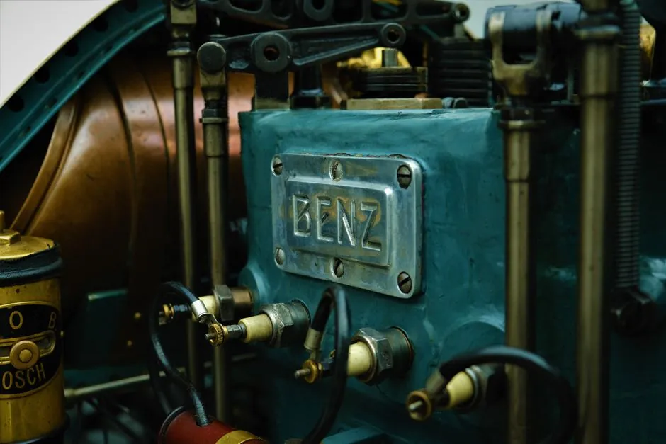
Plunger pump power ends fall into two families: crankshaft-driven units where plungers sit perpendicular to the input shaft, and wobble-plate (axial) units where a cam plate drives plungers parallel to the input shaft [S2].
Inside the crankshaft family, the horizontal triplex build with three plungers phased 120° apart is the workhorse configuration, because three overlapping discharge strokes flatten flow pulsation to roughly ±5% versus ±50% for a single-plunger unit [S1]. Power-end component groups consistently include the crankshaft, connecting rods, crossheads with wrist pins, and the frame that doubles as an oil reservoir [S3].
Power-End Anatomy: Crankshaft, Rods, Crossheads
The power end on a horizontal triplex pump is built like a small engine bottom end: a forged crankshaft runs in rolling-element main bearings, drives connecting rods through the crosshead guides, and transfers reciprocating motion to the plunger through a crosshead and wrist pin [S7]. The crankshaft must carry bending and torsional load simultaneously, which is why opposed-power designs on oilfield water-injection units route the dynamic load analysis through MATLAB plus ANSYS Workbench to verify static and fatigue strength at the crank pin [S4].
End play of the crankshaft is a controlled tolerance, not a wear target: GASO specifies a cold-measured end play not exceeding 0.003 inches to allow for thermal expansion under operating conditions [S5]. Crankcase oil splash-lubricates every moving part, with capacities ranging from 2 U.S. gallons (Series 3364) to 9 U.S. gallons (Series 3800), and SAE 90EP / AGMA 5EP or 6EP gear lubricants specified for average climates, with running oil temperature held below 180°F [S5].
Triplex vs Simplex vs Quintuplex: Pulsation and Frame Load
Plunger count and crank phasing directly set flow smoothness and dynamic load on the power end. A single-plunger (simplex) layout swings discharge flow by roughly ±50% per revolution, which forces oversized pulsation dampeners and accelerates fatigue on the crankshaft bearings; the triplex at 120° spacing cuts that swing to about ±5% [S1]. Quintuplex (five plunger) builds go further on smoothness but stack more crossheads into the same frame, raising the complexity of splash lubrication and crosshead-guide alignment.
The choice also depends on flow target: triplex units in commercial service commonly deliver 70 to 4,000 bar discharge pressure with delivered flow set by plunger diameter, stroke, RPM, plunger count, and volumetric efficiency [S1]. For a 25 mm plunger at 30 mm stroke, 600 RPM, three plungers, and 0.94 volumetric efficiency, the calculator on the same reference returns about 24.9 L/min (6.58 GPM), or 41.5 mL per revolution, at a mean plunger speed of 0.6 m/s [S1].
Drive-Side Options: Direct, Belt, Gearbox, Hollow vs Solid Shaft
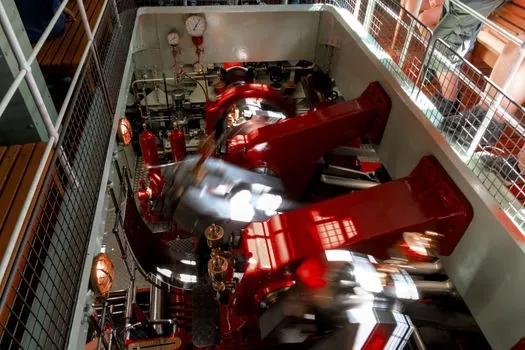
How the power end connects to the driver is the second configuration decision. The two most common mounting arrangements on high-pressure plunger pumps are direct drive and belt drive; gear reducers and integral motor flanges appear in packaged skids [S2]. As desired pressure and flow climb, so does the demand on the drive train, which is why heavier pressure classes usually move from belt to direct-coupled or gearbox-coupled layouts to control torsional vibration [S2].
On the crankshaft itself, manufacturers offer hollow and solid shaft variants. Hollow shafts let the pump mount directly on a motor face or accept a quill input, simplifying alignment; solid shafts suit belt or coupling drives and tolerate higher torsional input. Pump differentiation in the field comes down to whether the unit is driven by a crankshaft or wobble plate, cylinder count, piston (cup) versus plunger, lubrication method, and hollow versus solid crankshaft [S2]. Related plunger-count trade-offs, including the simplex to quintuplex spread, are covered in Plunger Pump Configurations: Simplex, Triplex, Quintuplex.
Bearing, Lubrication, and Crosshead Choices
Bearing selection is where the power end either lasts or fails. Main bearings on most horizontal triplex frames are rolling-element (ball or roller) for steady radial load under continuous duty, with the crankshaft forged for fatigue resistance at the journal transitions [S7]. Splash lubrication from the crankcase oil is the default on smaller frames, and for pumps below 150 RPM, oil level must sit at the crankshaft centerline to keep the dipper coverage reliable [S5].
Crosshead guides define how cleanly reciprocating load is transferred to the plunger; tighter guides cut packing wear but raise the risk of thermal seizure if lubrication lapses. The wet-crankcase layout, where the crankshaft runs submerged in oil, needs far less frequent attention than a splash-and-spray design, with manufacturer oil-change intervals typically set at 50 hours for break-in, then every 500 hours thereafter, using 30W non-detergent oil on smaller pressure-washer frames [S2]. Frame-level topics, including wear parts, overlap with adjacent process equipment such as the Rotor Wear Plates and Rubber Pads on Dry-Mix Shotcrete Machines: Specs, Wear Patterns discussion of high-wear rotating hardware.
Failure Modes That Trace Back to the Power End

Most plunger pump failures in the field are power-end problems wearing a fluid-end face. Cavitation on the suction stroke pits the ceramic plunger and cracks the packing within a few hundred hours when NPSH is short, with the acoustic signature of gravel-rattle in the cylinder and hammering discharge valves [S1][S2]. Inadequate downstream pulsation dampening cracks discharge manifolds on triplex units run too close to their surge frequency.
Plunger surface finish above Ra 0.4 µm chews packing in days rather than months, and plunger-to-packing clearance beyond about 0.05 mm drops volumetric efficiency below 90% with visible weeping at the lantern ring drain [S1]. Wet-crankcase plunger pumps also require a clean, non-detergent oil: multipurpose multi-viscosity gear lubricants are flagged as unsatisfactory for GASO-series triplex frames, with running temperature capped at 180°F before an oil cooler is recommended [S5].
Standards, Sourcing, and Selection Heuristics
Specifying a power end starts with three numbers: target flow in L/min, target discharge pressure in bar, and the NPSH available at the suction flange. Those three values fix plunger diameter, stroke, RPM, and the cylinder count, and from there the layout (simplex, triplex, quintuplex) and the drive type (direct, belt, gearbox) follow [S1][S2]. Material selection on the fluid end pairs with the power end: brass heads for soap solutions, stainless for severe service, and aluminum where pressure and chemistry allow [S2].
Before start-up, GASO triplex instructions require a relief valve in the discharge line set at the application-tag pressure, with the warning that closing the discharge against a running positive-displacement unit causes catastrophic destruction of pump, piping, or personal injury [S5]. Process-engineering context on how this fits into continuous plants is covered in OEE in Continuous Process Industries: Yes, With Specific Adaptations. For reference architecture on the plunger pump itself, the power-end subassembly is the mechanical subassembly that converts rotary input into reciprocating plunger motion, and the power distribution upstream of the driver sets the motor-side supply the drive is sized against.
Spec-level background on the components involved: power cable.