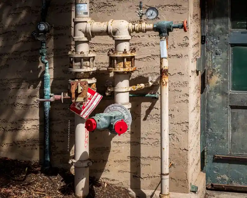
Quarter-turn pneumatic actuator installation collapses to five repeatable stages: depressurize and lockout/tagout (LOTO) the host line, size and mount the actuator to the valve with the correct bracket, torque the stem bolt and mounting nuts to spec, set the mechanical travel stops, then leak-test at 20 psig before any control wiring lands [S3][S5]. Skipping the air-gap setting on spring-return units is the single most common cause of stem-jam failures in service [S5].
This reference targets commissioning engineers, maintenance leads, and EPC sub-contractors who retrofit manual valves or replace failed actuators. It is not a controls-engineering tutorial for HART or Foundation Fieldbus positioner networks, and it does not cover hydraulic or electric actuator variants; for actuator selection logic before you reach the install bay, see the selection logic guide and the pneumatic actuator encyclopedia entry.
Pre-Install: Depressurize, LOTO, and Verify Sizing
Always work on a depressurized, isolated line: shut off the air supply, bleed trapped pressure to zero on a confirmed gauge, then apply LOTO before any hand tool touches the assembly [S2]. The Delco beginner guide explicitly lists safety glasses, cut-resistant gloves, hearing protection, and steel-toe boots as the baseline PPE, with hearing protection mandatory whenever the supply line is in noisy service [S2].
Sizing must be confirmed before bolting begins. The actuator output torque has to exceed the valve's break-torque at the worst-case differential pressure with a 25-30% safety margin, and the actuator's rated pressure class (commonly 80-120 psig supply) has to equal or exceed the available plant air [S3]. Spring-return single-acting and double-acting configurations have to be identified at this stage because the air-line plumbing is fundamentally different, and getting the wrong kit in place is the most expensive mistake to undo later [S2]. A pneumatic conveyor feed that ties into the same supply header should be checked for pressure sag under simultaneous start, since a starved actuator stalls mid-stroke and damages the stem coupling.
Mount the Actuator: Bracket, Bolt Pattern, and Torque
Actuator-to-valve mounting is a two-axis alignment problem. For quarter-turn units, the manufacturer-supplied bracket (typically ISO 5211 F03/F04/F05/F07 patterns) must be piloted on the valve top works, with the actuator output shaft centered on the valve stem within 0.5 mm of runout to prevent coupling wear [S4]. Bolt tightening follows a criss-cross pattern, not a sequential one, and is taken up in 3-4 passes to roughly one-third, two-thirds, then final torque, which prevents the bracket from cocking under load [S4].
Torque values are bolt-size specific, and the Delco reference table is a useful industry proxy: M6 at 8-10 ft-lbs (10.8-13.6 Nm), M8 at 18-22 ft-lbs (24.4-29.8 Nm), M10 at 35-40 ft-lbs (47.5-54.2 Nm), M12 at 55-65 ft-lbs (74.5-88.1 Nm) [S2]. Overtorque on a cast iron valve bonnet is the leading cause of bonnet cracks during commissioning; if the actuator flange is the load-bearing surface, the bonnet, not the flange, is what you are protecting. The MP8000 procedure (Johnson Controls) uses four metric nuts to secure the actuator to the yoke and requires hand-tight engagement of the valve stem into the connector before any air is applied [S5].
Couple the Stem: Adapters, Jam Nuts, and the 1/32 in. Air-Gap
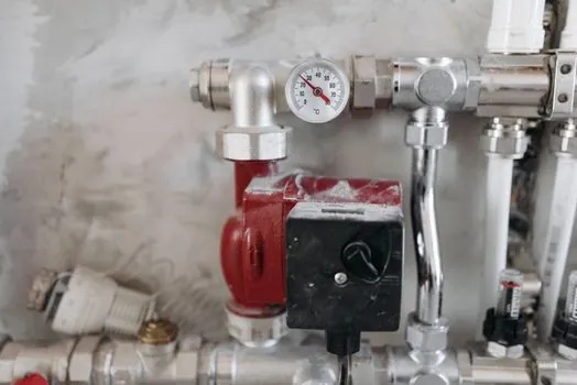
The stem coupling is the precision step. For linear units on iron flanged valves (MP8000 reference build), the procedure threads a 3/8-24 jam nut fully onto the valve stem, attaches the connector to the actuator stem with a 7/16-20 x 7/8 in. bolt (hand-tight only), then threads the actuator stop nut down to give roughly 1/4 in. of stem engagement before the anti-rotation pin is dropped through the yoke slot [S5].
Once 20 psig of air is briefly applied to move the stem 1/4 in. and the actuator stem bolt is torqued, the second jam nut (the lower one) is set to leave a 1/32 in. gap between the actuator stop nut and the brass bearing holder [S5]. This is the mechanical equivalent of a positioner's zero, and it is what the spring pushes against on a power-loss event. The 1/32 in. figure is not arbitrary: it is the clearance needed for thermal expansion of the brass bearing without binding, and skipping it is why spring-return units fail to fully stroke after 12-18 months in hot service [S5]. For threaded connections on the air-line side, PTFE tape or liquid thread sealant is applied to male threads only, with no sealant on the first two threads to avoid media contamination of the solenoid [S4].
Air Supply, FRL, and Tubing
Air supply quality determines actuator life. The standard conditioning train is an FRL (filter, regulator, lubricator) unit mounted within 3-5 m of the actuator, with a 5-micron particulate filter and a 0.3-micron coalescing filter for oil-free applications [S2]. Compressed air dew point has to sit at least 10 degC below the lowest ambient the actuator will see, otherwise moisture carryover corrodes the internal piston seals and the solenoid coil [S3].
Tubing sizing is a flow, not a pressure, decision. Delco recommends 1/4 in. or 3/8 in. OD nylon or polyurethane tubing for most solenoid-to-actuator runs, with the larger diameter used for strokes longer than 100 mm or cycle times below 2 seconds [S2]. Push-to-connect fittings (John Guest or SMC profile) are field-acceptable up to 150 psig; beyond that, compression fittings with a ferrule are mandatory. A general-purpose pneumatic supply at 80-100 psig is the typical working band, with the regulator set to whatever the actuator nameplate specifies, commonly 60 psig for compact quarter-turn units.
Commissioning: Leak Test, Stroke Check, and Fail-Safe Verification

Commissioning is a four-check sequence: (1) pressurize the actuator to 20 psig with the positioner in manual and watch for external leaks at all fittings and the stem seal for at least 60 seconds, (2) stroke the valve 3-5 full cycles to confirm smooth travel and verify the open and closed position indicators match the real disc position, (3) bump the supply to nameplate pressure and time the stroke, and (4) trip the fail-safe by venting the supply on a spring-return unit and confirm the valve travels to its safe position in under 2 seconds [S3][S5][S7].
The Powers Controls No. 4 pneumatic damper actuator (Siemens document 129-120) illustrates a parallel caveat for HVAC damper work: spring ranges are 3-7, 3-13, 5-10, 8-13, and 2-3 / 8-13 psi (21-48, 21-90, 35-69, 55-90, and 14-21 / 55-90 kPa) depending on the model, and the 3-7 psi unit is a hesitation model specifically built for unit ventilator outdoor-air dampers, not general globe-valve service [S1]. Picking the wrong spring range means the actuator cannot close the damper against the system pressure differential, which is a common cause of the damper drifting open after a power event. The fail-safe test is also when the pneumatic valve actuator is verified against the safety instrumented function (SIF) requirement, if the actuator sits in a SIL loop, and an unverified fail direction is the most common audit finding on brownfield retrofits.
Common Failure Modes and When to Replace, Not Repair
Three failure modes show up repeatedly in the first 12 months of service: leaking stem seals (root cause: gland nut not re-torqued after the first 50 thermal cycles), sluggish stroking (root cause: undersized supply tubing or a regulator set below actuator nameplate), and the actuator failing to reach the fully closed position (root cause: incorrect spring range for the differential pressure it has to overcome) [S1][S3][S7]. Each has a defined corrective action: re-torque to 1/6 turn past hand-tight per the MP8000 sequence, swap to 3/8 in. tubing or bump regulator pressure, and re-spec the spring range respectively [S5].
Replacement, not repair, is the correct call when: the diaphragm has visible set or cracking (no field-rebond kits restore original life), the piston seal groove is scored (re-bore is not possible on most compact actuators), or the spring has lost more than 10% of its free length (measured against a new unit of the same SKU) [S7]. For a linear guide-mounted actuator on a sliding-stem valve, also replace the linear guide block if any brinelling is visible, since a worn bearing transfers side load to the stem seal and you will be back in the same bay within six months. Documenting the as-found condition, torque values, leak-test pressure, and stroke time in the maintenance record closes the loop and gives the next shift a baseline for the next failure-mode hunt.
Trackable signals for the next commissioning window: the IEC 60534-8-3 reference on actuator sizing for control valves, and the FESTO or SMC technical bulletins on first 90-day seal break-in torque values, both worth pulling before the next batch of spring-return replacements lands on the bench.