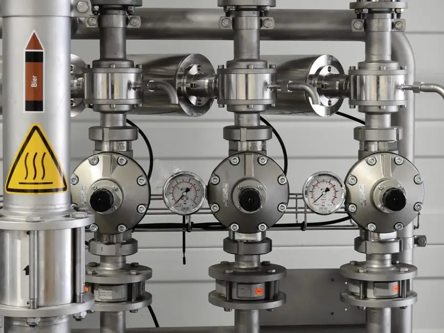
Pneumatic actuators are mechanical devices that convert compressed air energy into either straight-line (linear) or rotational (rotary) motion, and every industrial pneumatic actuator in service today can be sorted into one of two motion categories before any further sub-classification is attempted [S1][S2][S5].
Selection of the correct subtype is driven by the valve family it drives: linear motion feeds globe, gate, and pinch valves, while rotary motion (typically 90° quarter-turn) drives ball, butterfly, and plug valves, and the choice of energy source (pneumatic, hydraulic, electric) sits on top of that motion decision [S3]. Within the pneumatic family, the most common mechanisms are piston, spring/diaphragm, vane, rack-and-pinion, and Scotch yoke, and the dominant global sizing standards are ISO 15552 (standard cylinder), ISO 21287 (compact cylinder), ISO 6432 (round-body / mini cylinder), and the imperial NFPA tie-rod standard used in the United States [S2][S6].
Classification hierarchy: energy source, motion, mechanism, action
Actuators are first divided by the form of energy they consume, with pneumatic, electric, and hydraulic as the three industrial classes; pneumatic and hydraulic are both fluid-power devices, but hydraulic fluid produces roughly 25 times the force of a comparably sized pneumatic cylinder because liquids are virtually incompressible, which is why hydraulics dominate where very high force or shock-load holding is required [S2][S4].
Inside the pneumatic class, the next split is by output motion: linear pneumatic actuators (commonly called pneumatic cylinders) push a piston or diaphragm along a straight axis, and rotary pneumatic actuators swing a shaft through an arc, most commonly 90° for quarter-turn valves [S1][S5]. A useful one-line rule: linear pneumatic for rising-stem valves, rotary pneumatic for quarter-turn valves.
Mechanism is the third cut, and Wikipedia's taxonomy lists tie-rod cylinders, rotary actuators, grippers, rodless magnetic-linkage cylinders, and rodless mechanical-linkage cylinders as the canonical mechanical forms, with piston and diaphragm dominating the linear sub-tree and vane plus rack-and-pinion dominating the rotary sub-tree [S6]. The fourth cut, action, separates single-acting (spring-return, air moves one way, spring returns) from double-acting (air drives both directions); single-acting is specified wherever a fail-safe position is required on loss of instrument air [S5].
Linear pneumatic mechanisms: piston vs. spring/diaphragm
Piston-style linear actuators move a piston inside a cylinder: applying air pressure drives the piston one way, and venting or reversing air (or a return spring in single-acting) drives it back, producing either an Air-to-Extend or Air-to-Retract stroke depending on how the spring and supply port are arranged [S1]. Piston cylinders scale to high force and are the standard form for ISO 15552 (profile / tie-rod) and ISO 21287 (compact round-body) families, with ISO 6432 covering the small-bore round-body / mini cylinder segment [S2].
Spring/diaphragm actuators use a flexible diaphragm clamped inside a pressure-tight housing, with a spring behind the diaphragm providing the return force; air pressure on the diaphragm pushes the stem against the spring, so loss of air always yields a predictable fail-safe stroke [S1][S5]. This is the dominant form for industrial process control valve trim, especially in modulating control loops on globe valves, because the diaphragm area multiplied by supply pressure gives a clean, predictable thrust that pairs well with pneumatic positioners [S1].
A common industrial pattern is ISO 15552 profile cylinders for general factory automation (typically 32–100 mm bore, double-acting, magnetic-piston options for position sensing), ISO 21287 compact cylinders where envelope length is constrained, and ISO 6432 mini cylinders down to 8 mm and 10 mm bore for low-mass pick-and-place; in the US the same role is filled by NFPA tie-rod cylinders, with bore sizes offered in imperial inch increments and Quad-X style ring seals as a typical wear upgrade [S2].
Rotary pneumatic mechanisms: rack-and-pinion, vane, Scotch yoke
Rotary pneumatic actuators split into two main valve-automation styles: rack-and-pinion and Scotch yoke, with vane as a third, lighter-duty form [S1][S3]. Rack-and-pinion units use pistons with integral rack teeth that engage a central pinion on the output shaft; applied air pushes the pistons apart, the racks walk the pinion, and the shaft rotates through 90° (or 180° in some designs), giving compact double-acting torque in a symmetric package [S1][S3].
Vane actuators have a single movable vane fixed to the output shaft inside a cylindrical chamber, with air on one side of the vane swinging it through its stroke; the rotation is limited by the vane arc (commonly 90° or 180°), and the design is simple and inexpensive but lower in starting torque than a comparably sized rack-and-pinion [S1]. Scotch yoke designs convert piston linear force into torque through a sliding yoke, producing a non-linear torque curve that peaks near the end of stroke, which is favoured on high-torque quarter-turn service such as large butterfly and ball valves in oil and gas [S3].
Across these three rotary types, the practical trade is torque density vs. torque profile: rack-and-pinion gives a flat, near-constant torque curve ideal for throttling and modulating duty; Scotch yoke gives a rising-curve, high-breakaway torque that suits on/off isolation service; vane is the lowest cost but offers the least torque for a given envelope and is most often used on small ball valves and damper drives [S1][S3].
Single-acting vs. double-acting, and the fail-safe logic
Single-acting (spring-return) actuators use air to move the valve one way and a mechanical spring to return it, while double-acting actuators use air pressure for both strokes, so they have no fail-safe spring and need a separate reserve or a stored-air tank if a defined fail position is required on loss of supply [S5]. In practice, spring-return is the default where the safety case demands a known position (open or closed) when instrument air is lost, and double-acting is preferred where higher cycling efficiency, faster stroking, or longer spring life (springs fatigue with cycle count) matters more than the fail position [S5].
A useful way to read the comparison tables in the reference material: single-acting trades efficiency for safety, double-acting trades safety for efficiency, and rotary actuators in general (regardless of acting type) are described as more compact with faster response than linear equivalents, which is why the majority of new quarter-turn valve packages ship with rack-and-pinion rotary units [S5]. For a deeper supplier map and buy-decision logic, this spec-driven supplier walk-through pairs well with the mechanism taxonomy above.
Criteria-based comparison of the main pneumatic subtypes
Lining the four most common subtypes against four decision criteria, the picture is: spring/diaphragm linear wins on modulating control accuracy and cost, double-acting piston linear wins on cycle life and bidirectional thrust, single-acting rotary wins on fail-safe simplicity, and Scotch yoke rotary wins on breakaway torque for large quarter-turn isolation [S1][S3][S5]. The wider pneumatic fundamentals reference covers supply, conditioning, and FRL sizing, while pneumatic valve actuator and pneumatic actuator entries give deeper coverage of the actuator and valve-actuator subdomains specifically.
Cost is roughly proportional to bore, stroke, and torque rating, and is heavily influenced by certification (ATEX, IECEx, SIL) and body material (aluminum vs. stainless vs. carbon steel with epoxy coating); cycle life is dominated by seal material (NBR for general purpose, FKM / Viton for high temperature, EPDM for steam and chemicals) and by whether the unit is single- or double-acting, because springs in single-acting units are the cycle-life limit [S2][S5].
Matching pneumatic subtype to valve family and duty
For process control loops on globe valves, the spring/diaphragm linear pneumatic actuator is the default, paired with a pneumatic or electro-pneumatic positioner for 4–20 mA or HART control signals; for on/off isolation duty on small to mid-size ball and butterfly valves, rack-and-pinion double-acting rotary is the workhorse, and where the safety case demands a defined fail position, a spring-return rack-and-pinion rotary or Scotch yoke is specified instead [S1][S3][S5].
For factory automation (packaging, assembly, material handling), the pattern is ISO 15552 / ISO 21287 / ISO 6432 double-acting tie-rod or round-body cylinders with magnetic pistons for end-of-stroke sensing, sized from 8–10 mm bore up to 100 mm or 125 mm bore for heavier pushing; for low-profile clamping, the compact "pancake" short-stroke, large-bore form factor fills the envelope-constrained slot [S2]. A related field where the same fluid-power logic shows up is hydraulic accumulator installation, where the precharge-vs-system-pressure rule mirrors the spring-vs-air-pressure balance in a spring-return pneumatic actuator.
Limitations, failure modes, and where pneumatic is the wrong choice

Pneumatic actuators are not the right tool where the duty cycle is very high, where air supply is unreliable, or where the application cannot tolerate the compressibility of air: position accuracy under load is fundamentally limited by air spring effects, and stiction in older diaphragm units can be visible as deadband in a control loop [S2][S5]. Electric actuators are usually preferred where holding position with no air consumption matters (e.g. remote solar-powered sites, cleanrooms without compressed-air infrastructure), and hydraulic actuators are preferred where the required thrust exceeds what a reasonably sized pneumatic cylinder can deliver, or where very high static force must be held indefinitely without continuous air consumption [S2].
For broader equipment context, pneumatic actuators also show up as end-effectors on construction machinery and equipment (cabin tilt, brake actuation, tool positioning), and the same supply-and-conditioning logic that keeps them alive on a plant also feeds lamps and light fittings in hazardous-area lighting skids where air-driven indicator switches are still common; for the wider industrial lighting angle, see lighting equipment and electric lamps.
Trackable signals to watch over the next sourcing cycle: ISO 15552 bore-and-stroke cross-reference coverage by US distributors, the share of new builds that switch from single-acting spring-return to double-acting + smart positioner for SIL-rated loops, and any shift in default seal material (NBR → FKM) as process temperatures creep up in chemical and pharma plants.