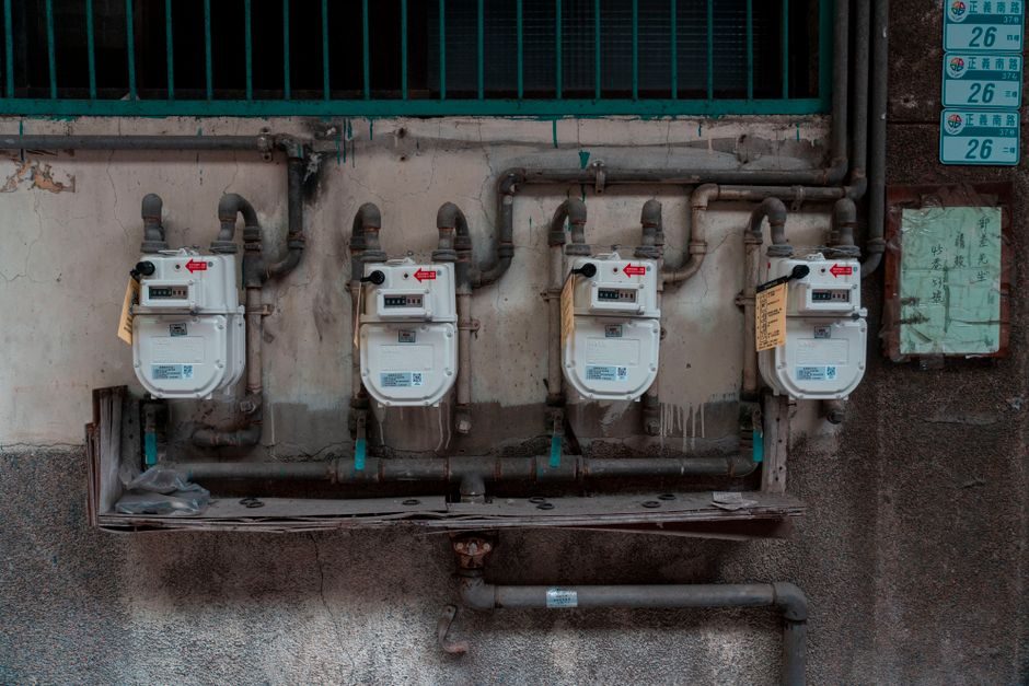
A pneumatic conveying system is a pressurised pipeline that transports dry bulk — powders, granules, pellets, flakes — using a gas carrier (usually compressed air or nitrogen) and a pressure differential generated by a blower, rotary valve, vacuum pump or venturi eductor [S2][S3].
Installation is not "bolt the blower to the floor, run pipe, switch on." It is a sequence of five physical gates — phase selection, material characterisation, line geometry, dust collection, and commissioning/ATEX handover — and a misstep at any one of them propagates downstream as pluggages, bend erosion, energy overspend or a failed area-classification audit. This guide walks those gates in the order a competent EPC or in-house engineer should run them.
Gate 1 — Phase Selection: Dilute vs Dense, Vacuum vs Pressure
Phase choice is set by the material's bulk density, particle size, friability and distance, and locks in the rest of the spec [S3]. Dilute-phase conveying operates at high air-to-material ratio (typically 25–80:1 by mass) and high velocity (15–30 m/s), moving fine non-friable powders over long distances through standard pipe; dense-phase conveying operates at low velocity (1–8 m/s) and high solids loading, suited to abrasive, degradable or friable materials [S3].
Vacuum (negative-pressure) systems are intrinsically cleaner — leaks pull inward, dust cannot escape into the workspace — and are preferred in pharmaceutical and food-grade builds; positive-pressure systems allow longer runs, multiple pickup points, and discharge into sealed receivers, and are the default for plastic, mineral and cement duty [S2][S3]. Most integrators quote both because the same OEM can deliver lean-phase vacuum for one line and dense-phase pressure for another on the same site [S2].
Gate 2 — Material Characterisation Before the First Pipe is Cut
Material characterisation is the step that separates a working install from a warranty call. Mills' design guide (2nd ed., 2004) treats conveying characteristics — particle size distribution, bulk density, angle of repose, moisture, hygroscopicity, explosibility Kst/Pmax, and minimum fluidisation velocity — as the input data for the entire scaling calculation [S3]. UK-based integrators offer a dedicated bench service to determine these properties before any geometry is drawn [S2].
Two material-driven watch-outs must be cleared at the desk: (1) combustible dusts (grain flour, sugar, aluminium, many pharma APIs) must be classified against IEC 60079-10-2 / ATEX 2014/34/EU zone definitions before the area classification drawing is issued, because this drives the motor, blower and receiver enclosure spec; (2) hygroscopic powders (WTA starch, certain salts, dried dairy) need a dew-point budget on the carrier gas — typically −20 °C PDP or drier — to prevent line-plugging mid-shift. If you cannot state Kst and MIE in writing, do not order the blower.
Gate 3 — Line Geometry: Bends, Gradient, Bore and Velocity Window

Most pneumatic conveying failures originate at the bends, and bend radius is the cheapest design lever you have. Vertical-to-horizontal transitions and gradient changes are the second most common plug point — a 5–10° fall on horizontal runs, or full-bore rodding ports at every 10 m of run, is the install norm.
Bore and velocity window are coupled: a 100 mm line conveying 2 t/h of PVC powder at 18 m/s is normal; the same line on 8 t/h of cement at 12 m/s is dense-phase. Get the bore wrong by one DN size and you either saltate (line wear) or settle (line plug). Mills' guide tabulates these windows per material family and is the reference most spec engineers keep open during layout review [S3].
Gate 4 — Dust Collection, Receivers and the Compressed-Air Side
Dense-phase and vacuum systems terminate at a receiver with integral filter, and that filter is the maintenance centre of the system — not an accessory. Filter area is sized for an air-to-cloth ratio of 0.8–1.2 m/min for fine powders (talc, cement, flour) and 1.5–2.0 m/min for coarser granules; cleaning pulse is typically 5–6 bar (oil-free) instrument air on a 60–120 s on / 20–30 s off cycle [S2][S3]. A receiver with the wrong filter media (e.g. polyester on a humid PVC line) loads within hours.
Carrier-air supply must be specified in m³/min at the line's working pressure, not at the compressor outlet, and must be conditioned: a refrigerated dryer to +3 °C PDP as the baseline, desiccant to −20 °C PDP for hygroscopic materials, and a 1 µm particulate + 0.01 ppm oil coalescer if the powder is food- or pharma-grade. The DIN/ISO pipework between [compressor → dryer → filter → receiver → conveying line] should be stainless or galvanised with tri-clamp or flanged joints, not push-fit, so leak testing at 1.5× working pressure is meaningful.
Gate 5 — Commissioning, ATEX Handover and Performance Verification
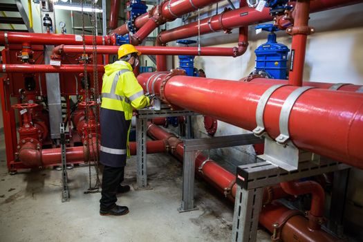
Commissioning is the gate the EPC schedule always compresses and the gate where the most expensive callbacks are born. A defensible commissioning pack contains: (1) a leak test of the conveying line at 1.25–1.5× working pressure held 30 min, with a documented pressure-decay ≤ 2 %/30 min; (2) a rotation and direction check on blower, rotary valve and pulse solenoids; (3) a step-load test at 25 / 50 / 75 / 100 % of design throughput, recording air consumption (m³/min), line pressure (bar), discharge temperature (°C), and receiver DP (kPa) at each step; (4) an ATEX/IECEx verification dossier for hazardous-area equipment including the dust-cloud zone drawing, EPL of each item, and the dust-ignition-proof certificate numbers [S2][S3].
Performance must be proven against the duty point on the datasheet — not "it pumps" — with at least 60 minutes of stable conveying at design t/h, then a 30-minute run on the worst-case material (highest bulk density or highest moisture) the line was specified to handle. Energy benchmarking belongs here: well-tuned systems deliver 30–50 % energy reduction over a legacy install at the same throughput, and integrators publish that as a measurable commissioning deliverable rather than a marketing claim [S2].
Common Failure Modes at the Installation Interface
Three failure modes recur at the install interface and are useful to design out at the drawing stage. First, rotary-valve air leakage on a positive-pressure system: if the discharge is at a lower elevation than the inlet, hot moist air migrates back through the rotor and packs the upper pockets with product; the fix is a venting bleed on the rotor housing plus a thermal cut-out. Second, venturi eductor air starvation on a vacuum system: a dedicated vacuum-rated side-channel blower with a 1.5–2× margin over the calculated m³/h prevents the system going dense-phase under upset conditions, with resulting pipe knock and filter collapse. [S1]
Third, the most expensive one: ATEX re-classification after install because a zone-22 area was drawn around the discharge but the integrator mounted a non-rated solenoid box inside it. Hazardous-area drawings must be issued before procurement, and every enclosure, gland, cable and junction box within the zone boundary must carry Ex tb IIIB or IIIC marking appropriate to the dust group. A useful pre-handover audit: walk the line with the dust-cloud zone drawing, mark every piece of equipment that crosses it, and verify the Ex marking physically on the nameplate.
Sourcing and Equipment Selection Notes
For 2026 builds, the live OEM pool covers the full phase/mode range: dense-phase pressure units with multi-nozzle venturi pumps (e.g. PRO280P-class) for short-haul powder/grain duty [S1]; continuous dilute-phase systems for fine and abrasive powders with controlled feed into mixing towers [S1]; and tailormade gravity-conveyor hybrids with venturi blower accessories for material-specific lines [S1]. Specialist integrators add in-house material-characterisation labs and a turnkey design–install–commission service [S2].
For the carrier-air side, a pneumatic cylinder or pneumatic actuator downstream of the receiver for divert-valve duty is a typical sub-assembly spec, and the line-side fittings — couplings, venturi nozzles, rotary-valve inlets — are covered under the pneumatic fitting category. When a system is built around a vacuum-side eductor or a venturi pump, the pneumatic conveyor selection itself is the dominant cost line, not the pipe. Two trackable signals: integrators publishing up to 50 % energy reduction on legacy retrofits [S2], and a continued shift to dense-phase and vacuum dense-phase for combustible-dust duty in food, pharma and additive manufacturing.
For related coverage, see Timing Belt Buying Guide 2026: Profile, Pitch and Spec Gates.