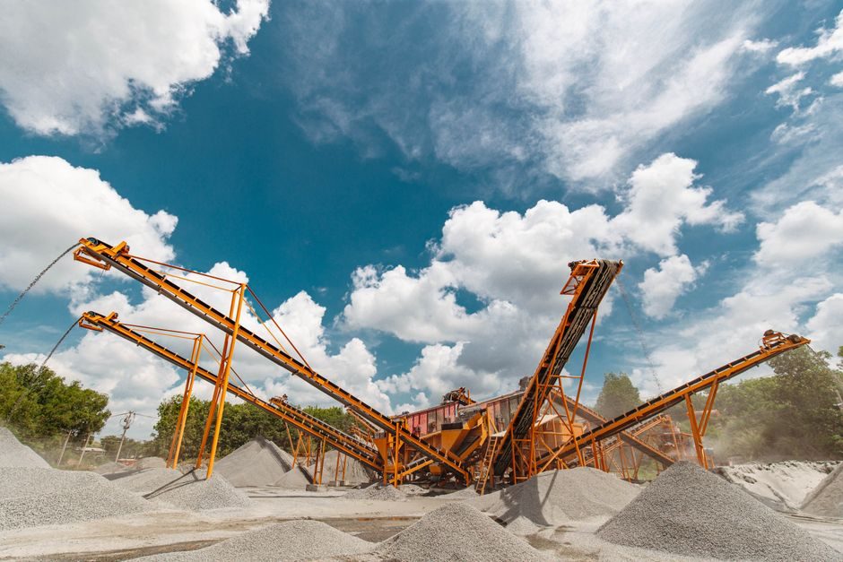
A pneumatic conveying system transports dry bulk solids — powders, granules, pellets — through an enclosed pipeline using either positive pressure or vacuum as the driving force, with the conveying gas most commonly air [S4]. In a vacuum system the maximum available pressure drop is roughly 1 bar, while pressure systems are typically used where higher line pressures and longer conveying distances are required [S8].
Two operational regimes dominate plant design: dilute (lean) phase conveying at high gas velocities and low solids loading, and dense phase conveying at lower velocities and higher solids-to-air ratios [S2]. The choice between them, plus a vacuum/pressure architecture, sets the entire cost, wear and energy profile of an installation.
Dilute vs Dense Phase: Two Regimes, Two Engineering Mindsets
Dilute phase conveying suspends individual particles in a high-velocity airstream and is the default for short runs, light materials and applications where product attrition is not critical [S4]. Dense phase conveying moves material as a moving bed or slug at solids-to-air ratios roughly an order of magnitude higher, which lowers line velocity, cuts particle degradation and reduces pipe wear [S2].
Pickup hardware changes with the regime. Pressure-system feeders include rotary airlock valves, blow tanks, dual-flap or dual-butterfly valve arrangements, and venturi ejectors, with selection driven by material properties, distance and required rate [S8]. For dense-phase blow-tank systems the feeder vessel itself is pressurised rather than mechanically metered, which lets the line run at much lower velocities than a rotary-valve-fed dilute line.
Pressure vs Vacuum: Where the Architecture Decides Itself
Vacuum systems are limited to roughly 1 bar pressure drop, which caps conveying distance and rate but keeps the pipeline under suction so any leak pulls inward — an advantage in dust-sensitive pharmaceutical or food operations [S8]. Pressure systems push the pipeline above atmospheric, allowing longer distances, higher capacities and multiple pickup points feeding a common conveying line [S8].
Closed-loop positive-pressure designs are the common pattern when a plant must feed several reactors or storage silos from a single source, while vacuum systems are favoured at central cleaning stations where OSHA and EPA dust exposure rules push the design toward sealed pickup [S1]. Both architectures rely on a pneumatic conveyor as the central moving element, with ancillary valves and controls setting the real operating envelope.
Decision Matrix: Dilute Phase vs Dense Phase vs Mechanical
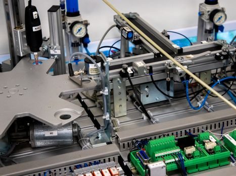
Across the four decision criteria that most often drive a CAPEX sign-off, the comparison is sharp. (1) Typical line pressure drop: vacuum ≤1 bar, dilute-phase pressure 0.3–1.0 bar, dense-phase pressure 1.0–3.5 bar [S8]. (2) Particle degradation: highest in high-velocity dilute phase, lowest in dense-phase slug flow [S2]. (3) Energy per tonne moved: dense phase at high solids loading typically beats dilute phase, with one Indian supplier publishing a 25% energy reduction claim on optimised conveying systems [S2]. (4) Capital and routing flexibility: pneumatic systems win on routing — pipes can go around obstacles, up inclines and through walls — versus mechanical conveyors that need straight catenary runs [S4].
Where pneumatic is the wrong tool: very high capacities above roughly 50–100 t/h over long horizontal distances, highly abrasive materials, and products that cannot tolerate any temperature rise from compressed air all push designers toward mechanical conveyors, screw feeders or pneumatic actuator-driven batch alternatives. For most mid-rate, sealed-route powder handling in chemical, food, glass, cement and pigment plants, the pneumatic route remains the default [S2][S4].
Where Pneumatic Wins: Enclosed Routing, Hygiene and Layout Freedom
Three engineering advantages are cited consistently across vendors and reference texts. First, complete enclosure: a pneumatic tubing network is dust-tight by default, which is why central vacuum systems are tied to OSHA/EPA in-plant cleaning rules and why suppliers like Pneuvay specifically list "decrease equipment maintenance" and productivity gains as a direct outcome of sealed routing [S7]. Scorpio Engineering markets a 90% dust reduction claim on optimised systems, paired with TUV-certified SS304 mirror-finish contact surfaces for food and pharmaceutical compliance [S2].
Second, layout freedom: the same source notes that pipelines can route in three dimensions, around existing structures and through multiple storeys, with no requirement for return runs — a contrast with mechanical conveyors that need straight catenary geometry [S4]. Third, labour and footprint: with no moving parts exposed to operators, a pneumatic silencer at the receiver drops exhaust noise below 85 dB(A) on typical installations, and the system can be reconfigured for new products or rates without civil-works changes [S1].
Where It Hurts: Energy, Wear, and Velocity Limits
The disadvantages are as concrete as the gains. Air-moving equipment — blowers, compressors, vacuum pumps — is the dominant operating cost, with dilute-phase systems carrying the highest specific energy demand because of the large volumes of air that must be moved per tonne of product. Dense-phase systems reduce this at the cost of more complex control and higher blow-vessel pressure ratings [S4].
Particle attrition and pipe wear are the second penalty: high line velocities in dilute phase fracture friable materials (food powders, catalysts, certain pigments) and erode elbows, particularly at the material-feed and direction-change points. Material limitations are hard — cohesive powders, moist or oily bulk, and very dense particles either plug lines or require specialised feeders and air management, which is why Mills' Pneumatic Conveying Design Guide dedicates an entire appendix to determining relevant material properties before sizing equipment [S3]. Distance is also bounded: even pressure-driven dense-phase systems run out of gradient over very long horizontal runs, and the design software market — PneuCalc is the long-standing dedicated tool for this — exists specifically because sizing by spreadsheet tends to fail on long lines and unusual materials [S5]. For comparison, the lifecycle cost mechanics on a related conveying class are covered in the overhead conveyor TCO breakdown — the same wear, energy and rebuild-cost logic applies to pneumatic lines once you map compressed-air kWh to dollars per tonne.
Who It's For — and Who Should Look Elsewhere
Pneumatic conveying is the right answer for: dry, flowable bulk under roughly 50 t/h, routes that need to change direction or elevation, and processes where dust control, hygiene or nitrogen blanketing are mandatory — food, pharma, fine chemicals, pigments, glass cullet, fly-ash [S2][S4]. It is the wrong answer for: very high tonnage over long horizontal distances, highly abrasive or cohesive bulk, products that cannot tolerate any heat of compression, and plants without a reliable compressed-air or blower supply [S3][S4].
A useful rule of thumb from the design literature: if the material can be characterised by a single Geldart group, a single conveying-air requirement and a known feed/discharge configuration, pneumatic will almost always win on layout and seal-tightness; if the material behaviour is unknown or the tonnage is near the upper end of dilute-phase capability, schedule a lab test first — vendors such as Whirl-Air-Flow operate dedicated dense- and dilute-phase test labs precisely so a customer can verify behaviour before buying hardware [S1]. The standards and data sources that anchor any final design are Mills' Pneumatic Conveying Design Guide for engineering methodology, manufacturer test data for material-specific behaviour, and OEM sizing software for line-pressure and air-requirement calculation [S1][S3][S5].
Trackable near-term signals worth watching: (1) PneuCalc Version 8 features released for designing or troubleshooting long-distance and high-pressure systems, which is a useful leading indicator of where the market is pushing line length and pressure [S5]; (2) Indian and South-East Asian EPCs publishing TUV- and SS304-grade dense-phase reference plants for food, glass and atomic-research end users, signalling tighter compliance baselines in those regions [S2].