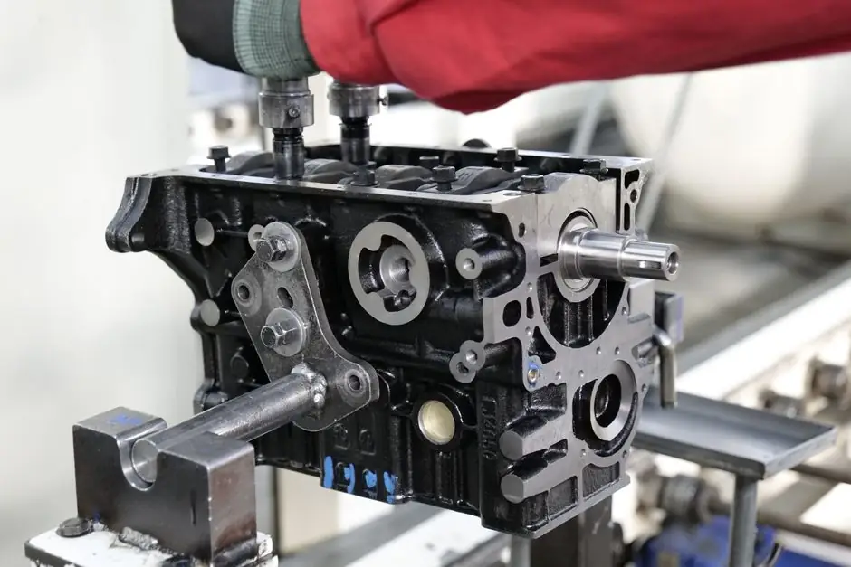
Two fixing points define every pneumatic cylinder install: the body and the piston-rod end, with the choice of rigid versus pivoting mount driven by whether the motion is straight-line or arc-following [S1]. For straight push, pull, or lift, bolt the body via tapped bottom holes, end-cap sleeve mounts, or a standard NFPA flange so the load travels down the cylinder centerline; for crank-driven motion, use a clevis, eye, or trunnion that lets the body swing without binding [S5].
Selecting a pneumatic cylinder starts with three decisions before any wrench turns: single-acting (spring or external return) versus double-acting (air on both sides for controlled extend and retract), bore size for the required output force, and stroke length to clear the working envelope plus any stop-tube allowance [S2][S4]. A pneumatic actuator that is mis-sized at the desk is the single most common root cause of field failures that get blamed on the installer.
Pre-Install Selection: Bore, Stroke, and Mount Family
Bore sets piston area and therefore theoretical output force at a given supply pressure; stroke must exceed the maximum required travel with margin for end-of-stroke deceleration and any internal stop tube [S2][S4]. For compact, short-stroke applications in tight envelopes, a compact pneumatic cylinder with tapped bottom or nose mounting is typically specified, while longer-stroke or higher-force builds call for ISO 15552 tie-rod or profile-barrel bodies with NFPA-compatible flange, foot, or trunnion mounts [S5].
Three mount families cover nearly every field install: rigid (flange MF1/FH, tapped-face MR1/UH, foot MS1) for static linear duty where the load tracks the rod centerline, and pivoting (clevis MP2, trunnion MT1/MT2, eye, rear hinge) for linkage applications where the cylinder must oscillate as the rod extends and retracts [S1][S5]. Side-lug (MS2T) mounts are used rarely because they create a bending moment off the cylinder centerline, so they should be avoided unless the application geometry forces the issue [S1]. For non-rotating rod duty on long lever arms, a double-rod or twin-rod configuration shares the bearing load across both end caps and is the correct choice over a stop-tube retrofit [S5].
Air Supply Preparation: FRL, Filtration, and Sealing
Connect the cylinder only after an FRL (filter, regulator, lubricator) train is in line: the filter removes particulates and condensate that score seals, the regulator holds supply pressure at the manufacturer's published value, and the lubricator (where specified) feeds oil into the air stream to protect dynamic seals [S2]. Air quality that does not meet the cylinder maker's spec is the most common upstream cause of seal swelling, bore scoring, and sticky cushions in double-acting units [S2][S4].
Seal every threaded pneumatic connection with the appropriate thread sealant or PTFE tape before installation; on speed-regulating valves this step is non-optional because a slow leak at the fitting looks like a cylinder fault and triggers hours of misdirected troubleshooting [S3]. Use only the fittings and hose ratings the manufacturer lists, and verify that hose flexibility is sufficient for any pivoting mount so the pipe work does not impose a side load back onto the cylinder port [S1][S3].
Mechanical Mounting: Alignment, Side Load, and Lubrication
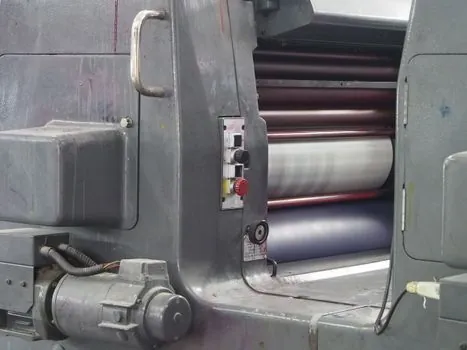
Side load is the most damaging condition a pneumatic cylinder can be asked to survive, so the first mechanical task is to confirm the mounting surface is clean, flat, and free of debris, then to align the cylinder so the rod load travels down its centerline [S1][S2]. Where perfect alignment is geometrically impossible, an alignment coupler or a die-set coupling at the rod end absorbs the residual mismatch and keeps the rod bearings from taking a constant bending moment [S1].
Vertical installations deserve a separate check: oil migration out of the cushion and seal area becomes a leak risk, and any rod-down mount should be reviewed for whether the application really needs rod-up gravity-assist or whether the seal kit is rated for the chosen orientation [S2]. Lubricate bearing slides and trunnion pivots on installation per the manufacturer's schedule, because a dry trunnion is the usual precursor to galling and to the load swinging off-axis mid-stroke [S1].
Pre-Commissioning Test Sequence
Before connecting the production load, drive the cylinder at the manufacturer's published minimum operating pressure using a flexible air line and a blow gun to confirm free travel and detect binding or excessive side load on the bare cylinder [S1]. For hydra-pneumatic and intensified cylinders, hold the test in the low-pressure approach and retract phases and do not command the high-pressure intensification stroke until tooling alignment is verified, because an offset load at full intensification force can bend a rod or fracture a mount in a single stroke [S1].
After mechanical test, pressurize the FRL-regulated supply to the set working pressure and command several full extend-retract cycles, watching for smooth cushioning at each end of stroke, stable mid-stroke speed under the rated load, and no audible air leak at the port fittings or rod seal [S2][S7]. A cycle that hesitates, chatters, or fails to reach full stroke is a stop-and-fix signal: do not load production parts onto an actuator that has not passed this acceptance test.
In-Service Monitoring and Maintenance Triggers
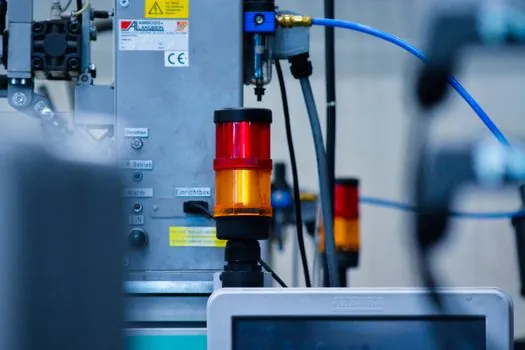
Symptoms map to root causes predictably: external air leak at the rod usually points to a worn rod seal or scratched rod chrome; internal leak across the piston (cylinder "creeps" under load) indicates a worn piston seal; slow or unstable speed under constant load points to insufficient supply pressure, a clogged FRL element, or cushion valve mis-adjustment [S4][S7]. Any rod that shows visible bending, chrome flaking, or scoring is no longer a repair candidate and should be replaced rather than re-sealed, because a bent rod will destroy the new seal within hours.
Scheduled tasks for a working cylinder are limited but non-optional: drain the FRL filter bowl on a documented interval, verify the lubricator reservoir level, re-torque mount fasteners to spec after the first 50 to 100 hours of operation as soft mounts settle, and re-check trunnion and clevis pin wear at every planned maintenance window [S2][S7]. Spare seal kits matched to the exact bore and model number should be kept on the shelf; a 5-minute seal swap on a planned stop beats an hours-long reactive callout when a seal finally lets go on a production line [S7].
When to Stop and Escalate
Stop the install and escalate when any of the following show up: the cylinder cannot reach full stroke at the manufacturer's minimum pressure with the production load attached, audible metallic contact is heard at end of stroke, the rod shows visible runout or scoring on first inspection, or the application duty cycle exceeds the catalog rating for the selected bore [S1][S4]. Pushing a marginal install into production transfers the cost from a one-time bench repair to an unplanned line stop, and on a pneumatic conveyor or linear guide line that share the same air header, a leaking cylinder will drag the whole circuit down. The cheapest path is always to validate the spec, the air quality, and the alignment on the bench before the cylinder is wired into the machine.
Trackable signals to watch over the next planning cycle: ISO 15552 bore-and-stroke standardization for new builds, FRL pre-assemblies with integrated pressure switches, and magnetic-piston cylinders paired with reed or solid-state switches for end-of-stroke verification on retrofit lines [S4][S5]. For a deeper procurement-side view on a related motion axis, see this surface roughness tester sizing and selection guide and this dosing pump spec-first selection for the same install-discipline pattern applied to measurement and fluid-handling skids.