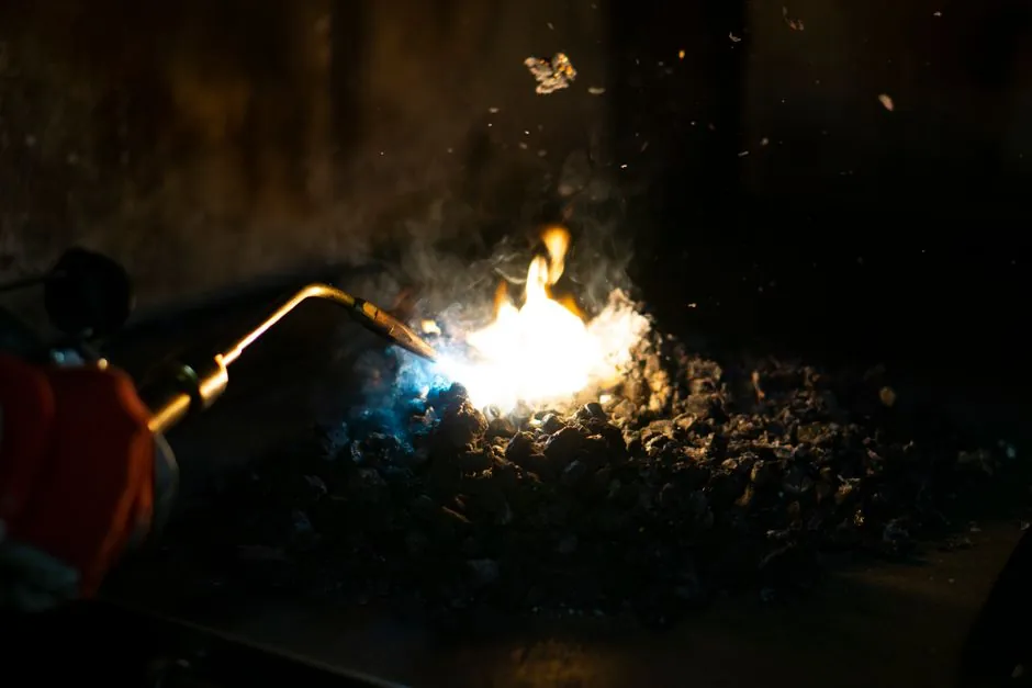
In a die casting cell the melting furnace, often called the pouring furnace when the metal is delivered directly, is the equipment that turns solid ingot, sow, and clean returns into a usable liquid alloy, while the holding furnace is the unit that sits next to the die casting machine and keeps that liquid at a tightly controlled pouring temperature for hours at a time [S1][S5].
The two units are not interchangeable. Melting requires a high thermal head to overcome the latent heat of fusion, typically operating several hundred degrees above the alloy liquidus for aluminum, while holding only needs enough input power to offset bath-surface and wall losses [S3][S5]. When a foundry tries to use one furnace for both jobs it usually pays the price in dross, oxide inclusions, and shot-to-shot temperature drift.
Where the Pouring Furnace Sits in the Cell
The pouring furnace is the upstream workhorse. Solid charge enters, fluxes are added, and the bath is brought up to a process temperature well above the alloy's liquidus before transfer to the cell, per supplier application notes on die casting foundry melting and holding layouts [S1].
Common pouring-furnace types in a die casting foundry include gas-fired reverberatory furnaces, stack (tower) melters, dry-hearth melters, electric induction furnaces, and gas-fired or electric crucible furnaces, each with different melt-rate, energy, and emissions profiles [S3][S5]. Cupola furnaces, induction furnaces, and gas-fired furnaces are explicitly listed as the most common melting units for aluminum die casting production [S5].
Key parameters for sizing a pouring furnace are hourly melt demand (kg/h), charge mix (ingot, sow, runner, biscuit), allowable tap temperature, recovery time after a cold charge, and the chosen fluxing and degassing practice [S1][S4]. The melt-rate requirement typically sets furnace rating, not the average daily tonnage, because surge events such as shift starts and alloy changes drive peak demand [S2].
Where the Holding Furnace Earns Its Keep
The holding furnace is the cell's thermal buffer. It receives molten metal from the pouring furnace (or a central melter via launder or ladle) and holds it within a narrow band, commonly ±5 to ±10 °C of the setpoint, so that every shot the aluminum die casting machine takes is at the same pour temperature [S1][S2].
Correct sizing is demand-driven, not capacity-driven. The hourly demand model uses casting weight, yield, shots per hour, machine count, shift pattern, and expected interruptions; peak demand and simultaneous refill events almost always govern the buffer more than the daily average [S2].
Operational controls on a holding furnace include minimum operating level, normal reserve level, maximum bath, alloy-change procedure, bath geometry, covers, and cleaning practice, because these variables determine oxidation, dross, and metal exposure time [S2]. Excessive inventory in a holder is not a safety factor, it is an energy and floor-load penalty that extends metal dwell time and increases hydrogen pickup [S2].
Central Melter vs At-Machine Holder: Layout Trade-Off
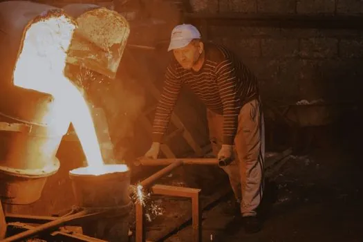
The classic cell layout question is whether to run one large central melter feeding several gravity die casting machine or HPDC cells, or to place a smaller dedicated holder at each machine, and the right answer depends on alloy segregation risk, transfer distance, cell traffic, automation level, maintenance access, and the number of casting machines fed [S1][S2].
Central holding consolidates inventory, simplifies fluxing, and lets a single alloy batch cover many cells, but the final launder or ladle transfer to each machine adds temperature loss and a new opportunity for oxide generation. At-machine holders shorten the last transfer, give per-cell thermal independence, and isolate a leaking or contaminated bath, at the cost of duplicated refractory, controls, and footprint [S1][S2].
For high-mix, high-alloy-change operations, the at-machine layout is usually favored because alloy changeover on a central 20-ton bath is a multi-hour event. For long, stable runs of a single alloy such as automotive structural castings, central holding plus launder delivery is typically more energy-efficient [S1].
Gas vs Electric Holding: The Selection Matrix
The two energy-source choices for holding furnaces, gas-fired immersion-tube and reverberatory designs versus electric immersion, resistance, or induction designs, behave very differently in a die casting cell, and the choice should be made against the same duty cycle [S2][S3].
Gas holders suit sites with economical fuel, high recovery demand, and existing gas infrastructure, and they typically accept large volumes of cold charge and scrap returns quickly, but they bring combustion byproducts into the cell, demand exhaust and emissions permits, and need regular burner and tube service [S2][S3]. Electric holders offer clean, quiet operation at the unit, precise temperature control, and simpler permitting, but they require adequate electrical capacity and show longer recovery times after a large cold refill unless the kW rating is generously sized to peak demand [S2][S3].
What the Pouring Furnace Controls, What the Holder Controls

The pouring furnace controls melt rate, charge flexibility, and alloy chemistry at the upstream end, while the holding furnace controls pour temperature stability, dross generation rate, and hydrogen pickup at the machine end, and confusing these roles is the most common source of cell-level quality problems [S1][S5].
By keeping the molten metal at a consistent temperature, holding furnaces prevent defects such as shrinkage, porosity, and uneven filling that show up when the die casting die sees a drifting bath temperature shot after shot [S7]. Melting furnaces, by contrast, must deliver clean, well-fluxed, well-degassed metal at the right superheat, because no amount of holding can fix inclusions or dissolved hydrogen introduced upstream [S4][S5].
For magnesium work the same split applies but the safety constraints tighten, which is why magnesium die casting machine cells are typically served by dedicated, sealed, flux-protected holding furnaces rather than the open-bath designs common in aluminum cells. The downstream casting-process reference for general die casting cell design sets the framework the furnace system has to feed.
Common Failure Modes and Cell-Level Limits
The three failure modes that show up most often in die casting furnace systems are: (1) bath-temperature drift in the holder caused by undersized kW input versus peak refill demand, (2) dross blow-up in the pouring furnace caused by excessive flux or excessive bath turbulence during transfer, and (3) hydrogen-driven porosity in the casting caused by long metal dwell time in a holder that is much larger than the hourly demand profile needs [S2][S4][S7].
The practical mitigation for the first is to size holding kW to peak recovery, not average loss; for the second, to use bottom-pour or well-designed launder transfer with minimum drop height; and for the third, to keep the holder inventory at 1-2 hours of peak demand rather than a full shift's worth [S2].
Refill strategy is itself a control variable: the melter, transfer system, and holder must be evaluated as one thermal process, because a large cold refill into a small holder will swing the bath out of its control band even with adequate kW, and that swing is what produces out-of-spec shots for the rest of the recovery window [S2].
Standards, Sourcing, and Engineering Acceptance
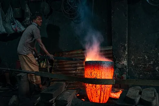
For a useful equipment review on either furnace, record alloy, charge form, hourly and peak demand, operating temperature, schedule, utilities, material movement, controls, emissions, layout, and acceptance criteria, then compare vendors against the same duty cycle rather than catalog capacity [S2]. Notable suppliers cited for melting equipment include Nabertherm, Otto Junker, and StrikoWestofen, while StrikoWestofen and Zhejiang Rongda are cited for holding equipment [S5].
Lindberg/MPH catalog product families such as the Gas-Fired Reverberatory Furnace, Stack (Tower) Melter, Dry Hearth Melting Furnace, Electric Immersion Aluminum Holding Furnace, Electric Coil Stationary Holding Furnace, and Gas-Fired Holding Furnace illustrate the standard split between upstream melting and downstream holding hardware used in U.S. die casting foundries [S3].
Trackable signals to watch over the next planning cycle: rising electric-holder kW ratings in catalogs aimed at larger cold-refill recovery, more launder-based central-melter-to-cell layouts in new structural casting plants, and tighter emissions limits that will continue to push cell-side holding toward electric immersion designs for aluminum die casting work. For context on the broader casting-cell tooling decisions that the furnace system has to feed, see this guide on pit molding vs flask molding for very large castings.