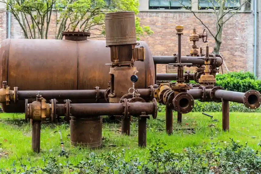
A spring-loaded diaphragm PRV belongs on the main supply line, just past the main shutoff and before the first branch tee, so every downstream fixture, hose bibb, and water heater sees the same regulated pressure [S1][S5]. Factory setpoint is 50 PSI across most residential units, with a usable adjustment window of 25 to 75 PSI; the high-end Watts LFN45B family accepts inlet pressures up to 400 PSI within that same outlet band [S1].
The job is not just to drop pressure, it is to hold a flat outlet curve while the street pressure wanders between roughly 75 PSI at peak demand and 120 PSI at 3 a.m., which is why a simple ball valve substitution will not work [S1]. The install sequence, isolation layout, and downstream instrumentation (a pressure gauge on the outlet is mandatory for setpoint verification) are the difference between a PRV that quietly does its job for a decade and one that hammers, chatters, or fails diaphragms inside two years [S1][S2].
Sizing and Certification: Get These Three Numbers Right Before Cutting Pipe
Pipe size match, certification, and connection style are the three pre-cut decisions that decide whether the install passes inspection and survives the first pressure cycle. A 3/4 in. PRV is standard for most residential mains and is rated for roughly 20 GPM; stepping up to 1 in. is typical for larger homes or light commercial at about 32 GPM, while 1-1/4 in. to 1-1/2 in. units cover multi-unit or commercial runs in the 42 to 60 GPM band [S1].
Any PRV on a potable water line must carry NSF 61 and NSF 372 lead-free certification, and that is non-negotiable for code compliance [S1]. Connection style should be union-end or double-union on both sides, because the strainer needs periodic cleaning and the diaphragm eventually wears; without unions, every service call becomes a pipe-cutting job [S1]. For selection logic that applies the same scrutiny to a related instrument family, see the Pressure Sensor Selection: Range, Reference, Accuracy, Output, Media spec map.
Where to Mount It: After the Shutoff, Before the Water Heater, With Service Access
Three placement rules cover nearly every residential and light-commercial install, and each one fixes a specific failure mode if violated. First, the PRV goes on the main supply line, just past the main ball valve shutoff, before any branch tees to hose bibbs, water heaters, or interior plumbing, so the whole downstream network is regulated [S1]. Second, the PRV must sit upstream of the water heater, because pressure reduction has to happen before the water is heated; otherwise thermal expansion at unregulated pressure is what waterlogs expansion tanks, weeps T&P valves, and kills appliance warranties [S1].
Third, the unit has to remain accessible: a bell-shaped or dome-shaped brass body, often with an adjustment screw or bolt on top, that homeowners and techs can reach for screen cleaning and setpoint re-checks [S1][S5]. Typical physical locations include right after the main shutoff, outside near the water meter, or inside a utility closet or mechanical room, with the shutoff-to-PRV spacing kept short so the regulated zone starts at the building entry [S5].
Upstream and Downstream Layout: Isolation Valves, Y-Strainer, Gauges, Optional Bypass
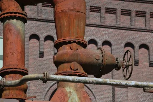
A PRV only behaves predictably when the surrounding piping gives it a stable, debris-free inlet and a verifiable outlet. The standard assembly sandwiches the PRV between two full-port isolation ball valves, with a Y-strainer upstream to catch debris before it scores the diaphragm or seat, and pressure gauges on both the inlet and outlet sides to read the differential in real time [S1][S2]. A 0 to 100 PSI gauge downstream of the PRV is the minimum instrumentation for setting and verifying the outlet; without it, setpoint adjustment is guesswork [S1].
For high-stakes or continuous-duty industrial runs, the spec'd layout also includes a bypass line so the system stays in service while the PRV is rebuilt [S2]. The pressure gauges and rubber O-rings on the assembly should be removed before any heat-based joint work and reinstalled only after the body has cooled, otherwise the elastomers are damaged on the way in [S2]. For a parallel decision framework on another inline fluid-control component, the Needle Valve Advantages and Disadvantages: Spec Map for 2026 Selection guide uses a similar isolation-and-instrumentation logic.
Adjustment Procedure: Lock the Outlet, Then Verify Under Flow
Setpoint is a static number; the verification is dynamic. Inlet pressure is measured first with a gauge on the hose sill or a downstream bibb, and a PRV is only installed if the reading actually exceeds the safe band for the downstream fixtures [S2]. Once the unit is in the line, the adjustment screw is turned clockwise to raise the outlet pressure and counter-clockwise to lower it; the spring preload is what the diaphragm fights against, so this is a one-to-one mechanical relationship, not an electronic trim [S3].
After adjustment, the verification step is non-optional: turn the main supply back on with a downstream faucet open, then read the downstream gauge while a fixture is running and again with everything closed. A PRV that holds 60 PSI under both no-flow and loaded conditions is passing; one that droops more than a few PSI under flow is undersized or has a fouled strainer [S1][S2]. For systems that need a verifiable reference reading during commissioning, a pressure calibrator on the outlet gauge loop is the next step up in audit trail.
Failure Modes, Thermal Expansion, and When to Replace Instead of Repair
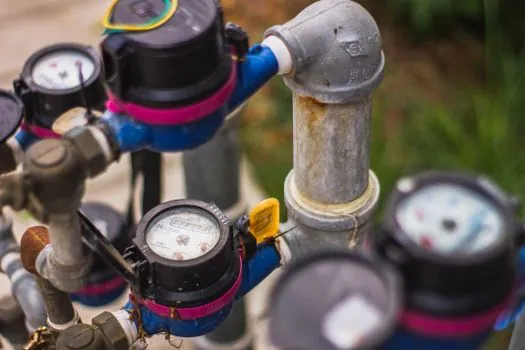
The three failure modes that show up most often in service are all predictable, and each one points back to either sizing, placement, or a missing companion component. A PRV that chatters or whistles usually has an undersized strainer, debris on the seat, or an inlet pressure that is hunting because the unit is the wrong size for the available flow [S1]. A PRV that holds setpoint but lets the water heater T&P valve drip is being asked to absorb thermal expansion it was never designed to handle; the correct fix is a potable water expansion tank on the cold side, not a higher PRV setpoint [S1].
A PRV that will not adjust, or that drifts more than about 5 PSI over a week, has a fatigued diaphragm or a fouled seat and belongs on the bench for rebuild, or on the truck for replacement if the body is more than 8 to 10 years old [S1][S3]. If a safety relief event is possible downstream, a separate safety relief valve must be present and rated for the now-regulated pressure, not the street pressure, or the system is unprotected at the new lower setpoint.
Installation Walkthrough: 13-Step Field Procedure
The field sequence that ties the above rules into a single pass is well documented across the trade and collapses cleanly into 13 steps [S2]. Measure the inlet pressure at a hose sill with a gauge; if it is above the safe band for the building, plan the PRV install. Fit threaded fittings and pressure gauges to both ends of the planned PRV assembly and mark the cut location on the main. Shut the main supply, drain the line, and cut the marked section with a tubing cutter [S2].
Remove the gauges and O-rings from the assembly, flux the joint ends, then sweat or weld the body into the line. Reinstall the gauges and O-rings only after the assembly has cooled, then add a downstream gauge and slowly open the main to pressurize. Adjust the screw counter-clockwise to back the spring off, then clockwise to bring the outlet up to the target setpoint (typically 50 to 60 PSI), and lock the adjusting nut [S2][S3]. For broader procurement and TCO context on a related inline valve family, the Needle Valve TCO: Material, Pressure Class, and Sourcing Cost Drivers piece follows the same install-then-verify discipline.
Track these signals on the next service interval: downstream pressure under flow and at static, both compared to the same setpoint within about 3 PSI; strainer cleanliness on the annual check; and any T&P valve discharge on the water heater, which is the early warning that thermal expansion is no longer being absorbed by the expansion tank. A second verifiable node is the inlet-side gauge reading; if street pressure has crept above 100 PSI, the PRV is doing more work and the diaphragm life is shorter than the nameplate estimate.