
An MCC elevation drawing reads as a two-axis grid: columns (vertical sections) are numbered left-to-right starting at 1, and unit positions inside each column are lettered top-down A, B, C, D, E, F, G, H, J, K, L, M, with the letter I skipped to avoid confusion with the numeral 1, per the convention most US panel builders and OEMs follow [S2].
The label you see on each bucket door (e.g. "3D") is therefore a compact map coordinate: column 3, fourth unit position from the top. Reading it that way lets you walk straight from a schematic reference to the physical compartment, and straight back again during lockout/tagout [S1][S2].
Section Numbering: Left-to-Right Columns, Starting at 1
Column numbering on an MCC front elevation is the ordinal of the vertical section as it sits in the lineup, with the leftmost shipping section designated column 1 and numbering increasing by 1 to the right, regardless of section width [S3]. A standard 600 mm wide section sits next to a 1000 mm wide one, but they still consume consecutive column numbers, which is why EasyPower and similar tools key the elevation to a Column Number field rather than a physical X-coordinate [S3].
Field practice inside plant electrical rooms matches this rule: the first bucket at the top-left of the lineup is almost universally "1A", and deviations from that pattern are plant-specific rather than industry-standard [S2]. When you inherit a new facility and the leftmost top bucket is labeled "1B", treat the entire lineup as a local dialect and do not assume standard numbering until you confirm it against the as-built drawing set [S2].
Unit Lettering: A at the Top, M Near the Bottom, No I
Inside each column, unit positions are lettered top-down, and the standard NEMA bucket height is 6 inches (roughly 152 mm) per unit, with multiples stacked vertically. A typical 72-inch-tall section can therefore hold 12 unit positions (A through M, minus I), which lines up with the common 12-space frame sold by Allen-Bradley, Eaton, Schneider, and ABB [S1][S2].
The letter I is omitted by convention to prevent misreads against the numeral 1 on bucket nameplates and one-line diagrams, so a fully populated 12-space section reads A, B, C, D, E, F, G, H, J, K, L, M from top to bottom [S2]. When you see a label like "1A" on a single 6-inch bucket, it is one unit high; if the label is "1A/1B", the bucket spans two unit spaces and consumes both letter slots [S1].
Bucket Size Notation: Modular Heights in Column-Width Multiples

On the elevation, every bucket is drawn as a rectangle whose height is a multiple of the standard 1X (one unit) space. A 2X bucket is twice as tall and carries two letter positions; a 3X bucket carries three, and so on up to the full-section main breaker or starter, which can swallow 4 to 6 unit spaces [S3]. EasyPower encodes this as the Starter Space field, defined as "height of the space in terms of the column width", and the rendering tool stacks multiple items in the same column in the order they are entered in the Description spreadsheet [S3].
This is also why a label like "3D" does not tell you the bucket's physical dimensions; you need the elevation's height tick marks or the OEM's outline drawing to confirm whether D is a 1X FVNR starter or a 2X VFD bucket. The MCC cabinet reference page covers the standard NEMA frame dimensions and how they map to bucket sizes.
Reading a Real Label: From "3D" to the Schematic
Trace an example: a bucket labeled "3D" in a 5-section lineup means column 3, fourth unit position from the top. Open the OEM one-line drawing for the project, find the column-3 riser, and locate the device at unit D; that is the same motor starter or feeder you are about to lock out [S1][S4]. The bucket nameplate itself repeats the same coordinate plus the catalog number, serial number, horsepower, and NEMA enclosure type, which is what you read during commissioning and what you cross-check against the hydraulic power unit or driven-equipment nameplate before energizing [S4].
For PLC integration projects, the convention is to mirror the MCC coordinate into the PLC tag name, so a VFD at "3D" controlling a 50 hp pump might be tagged MCC3D_PUMP01_RUN, which keeps the tag, the bucket label, and the schematic reference aligned in the same string [S5]. When that discipline is missing, you get the most common integration error: the PLC program references "MCC3D" but the as-built shows the VFD landed at "3E" because the bucket was resized during FAT [S5].
Variants and Exceptions: Bottom-Up and Plant-Specific Dialects
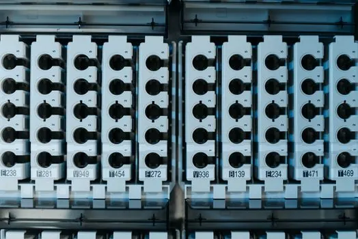
Not every plant follows the top-down letter rule. In one paper-mill example discussed in a 2013 forum thread, the existing facility numbered from the bottom of each column, so the top starter read "1B" instead of "1A" and the next bucket read "1D" for a 2X unit [S2]. Engineers responding to the thread agreed that no single binding industry standard governs the choice, and the only requirement is internal consistency between the bucket labels, the elevation drawing, the one-line, and the PLC I/O list [S2].
Practical advice when you hit a non-standard plant: pull the as-built elevation, walk the lineup, and confirm at least three random buckets match the drawing before you trust the numbering for any lockout. If you are the engineer standardizing a new plant or commissioning a greenfield MCC, lock the convention in the project specification (top-down, skip I, A starts at column 1) and require the OEM to label buckets accordingly at the factory, which is cheaper than re-labeling in the field [S1][S2].
Wiring, Wireways, and What the Elevation Does Not Show
Front elevations show bucket positions and section widths but deliberately omit most internal wiring; that detail lives in the schematic and wiring diagrams referenced by the same column/unit coordinate [S1]. The top and bottom horizontal wireways and the vertical wireway between columns are usually drawn as a thin strip on the elevation, with height settable in the drafting tool, and they carry the control wiring between buckets and out to field devices [S3].
For thermal and environmental layout, the elevation also drives the coolant distribution unit and FRL unit placement in adjacent panels, because the MCC's vertical wireway is the practical path for shared pneumatic and control tubing when the lineup is built into a process skid. Sand reclamation systems, by contrast, are normally sited in a separate enclosure downstream of the MCC, and their only electrical connection is a feeder breaker that shows up as a tall unit position in one of the columns [S1].
Common Errors When Reading a New MCC Elevation

Three mistakes show up repeatedly. First, assuming the leftmost section is column 1 when the lineup is actually drawn in mirror image because the customer faces the back of the gear; always confirm orientation against the plan view, not the elevation [S1][S3]. Second, treating a 2X or 3X bucket label like "3C/3D" as two separate loads; it is one device, one catalog number, one lockout point, and it consumes two letter positions on the column [S3]. Third, reading the label without checking the degassing unit or external-process interlocks, because some bucket positions are reserved for special-function starters (reduced-voltage, reversing, two-speed) whose schematic pages sit outside the standard one-line folder.
A useful audit step before any energization is to print the elevation at full size, walk the lineup with a tape measure, and confirm that each bucket's physical height in inches matches its unit-letter count at 6 inches per unit. Mismatches of even one unit position are a red flag that the as-built drawing is stale and needs a re-mark before you rely on it for maintenance or PLC mapping [S1][S5].
How This Connects to Modern PLC Integration
The 2026 best-practice guide for PLC-to-MCC integration treats the elevation coordinate as the single source of truth for tag names, drawing hierarchy, and cross-references between the one-line, the schematic, and the PLC I/O list [S5]. A disciplined project stamps the column/unit coordinate onto every drawing in the title block, so a search for "3D" returns the right schematic page, the right bucket nameplate, and the right PLC tag without manual lookup.
That discipline pays off most during troubleshooting, because field electricians and control engineers can read a single label and reach the same schematic page in under a minute. It also scales across MCC-to-MCC lineups, where a 12-section lineup can hold 144 unit positions and a single off-by-one labeling error propagates into every downstream drawing if it is not caught at the factory acceptance test [S3][S5]. The simple reading rule is the one to keep on the truck wallet card: column number on the bottom, unit letter on the top, A at the top of the column, 1 at the left of the lineup, and I never appears.
Trackable signals for the next 6-12 months: watch for IEC 61439-1 updates that may pull low-voltage MCC assembly rules into stricter marking requirements, and watch whether NEMA releases a formal numbering guidance document, since the current de-facto A-through-M-skipping-I convention is still maintained by OEM house style rather than a published standard [S1][S2]. A practical near-term action is to audit one of your own MCC elevations against the bucket door labels and the PLC tag list; any drift between those three is a candidate for a re-mark or re-tag project before it becomes a lockout incident.
Background reading: How to Read Ohm and Wattage Markings on a Brake Resistor.