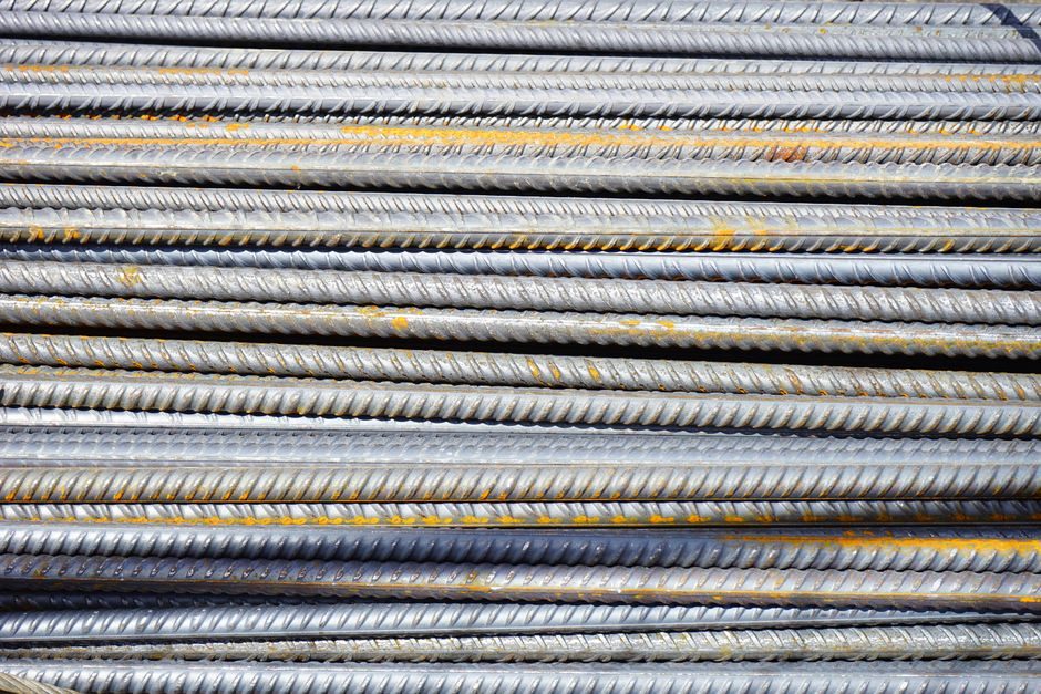
A rebar threading machine only delivers code-acceptable splices when the bar end is square, the machine is sized to the rebar diameter, and the rebar coupler is torqued to a documented value with a calibrated wrench [S1][S2].
This guide covers parallel-thread systems on Grade 500/500B/HRB600 bar from 12 mm to 40 mm, the diameter band where most field threading machines are sold by Chinese and Indian OEMs (HBMC, BARTECH, Jindi, Surya Engineering) [S1][S2][S4][S5]. For background on the parent product, see the rebar threading machine encyclopedia entry and the related rebar bender reference.
Two Machine Families: Cut-Thread vs Roll-Thread
Cut-threading machines (model patterns CRS40, CTM40, CRS39/CRS50) remove material with a tangential chaser and are typically used for short production runs, smaller diameters (≤ 32 mm), and on-site repair where a portable unit is needed [S1][S2].
Roll-threading machines (model patterns CDRG-45, DRT32S, RTM40-100/200/300/400) plastically deform the bar surface, preserve the parent-metal cross section, and reach higher fatigue life; the RTM40 series covers 100–400 mm thread lengths for 16–40 mm bar [S1][S2]. For the material being threaded, the rebar grade determines both pre-upset need and machine tonnage.
Pre-Install Site Acceptance: Power, Anchor, Coolant
Three-phase 380 V / 50 Hz supply with a dedicated breaker sized to the nameplate FLA is the standard supply seen across CTM40, CDRG-45, and RTM40-series machines from Chinese OEMs [S1][S2].
Anchor the machine body to a level concrete pad through its four base holes with M16 chemical or expansion anchors torqued to ~120 N·m; verify level to ≤ 0.5 mm/m across the bed before bar-end prep, otherwise skew cuts into the die and shortens chaser life [S1][S4].
Roll-threading units need cutting fluid or water-soluble coolant at 8–12 % concentration supplied to the rolling zone; cut-threading units run drier but still require periodic chip evacuation [S1][S2].
Bar-End Preparation Sequence
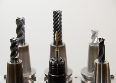
Step 1: cut the bar square with a rebar cutter-type saw or shear; a cut that is more than 1.5° off perpendicular forces the die to mill a tapered thread and reduces engaged length [S4].
Step 2: for HRB600/Grade 600 bars or any bar ≥ 32 mm, upset the end first on an upsetting machine (LD1800, RUM40C, RUM40D patterns from HBMC) to enlarge the cross section by 1.2–1.3× before threading; the upset end is what the parallel threads cut into [S1][S2][S4].
Step 3: peel the deformation ribs at the thread zone on rib-peeling models (RTM40-300) or feed directly into the rolling dies on standard models; the rib-peel step adds ~3–5 s per end but is required when the as-rolled rib height would otherwise lift the rolling dies off the bar surface [S1].
Threading Pass: Spindle Speed, Feed, and Lubrication
Set spindle RPM to the OEM table value for the bar diameter — common values are 30–50 RPM for 16–25 mm bar and 15–25 RPM for 32–40 mm bar on RTM40-series machines [S1][S2].
Full thread length on a standard parallel-thread coupler is 1.0–1.5× the bar diameter per side, giving a total engaged length of 2.0–3.0× D inside the coupler; verify with the coupler's gauge before the first production cut [S1][S2][S5].
Stop the machine when the thread reaches the marked length on the bar, not when a foot-switch timer expires; a stop short of the mark under-engages the coupler, a stop long wastes bar and may bottom out the die [S1].
Thread Acceptance: Plug and Ring Gauge
Every threaded bar must pass a GO thread ring gauge (large end of the coupler), and every coupler must pass a GO/NO-GO thread plug gauge (TAP) before assembly — the GO gauge must enter by hand, the NO-GO gauge must not enter more than 2 turns [S1][S2][S5].
Reject and re-cut any thread that shows chipped crests, torn flanks, or an out-of-tolerance pitch diameter; do not attempt to chase a damaged parallel thread back into spec — the standard field remedy is to cut the bar back by one full thread length and re-thread from a fresh shoulder [S1][S5].
Mark gauged threads with a paint pen to prevent accidental re-use of a rejected end after the bar has been re-cut and re-threaded [S1].
Coupler Makeup: Torque Wrench and Acceptance
Hand-tighten the coupler onto the first bar until the threads are fully engaged, then align the second bar, hand-tighten it in, and finish with a calibrated torque wrench — typical target torque bands reported by Chinese and Indian coupler suppliers for parallel-thread systems are in the 200–350 N·m range for 16–32 mm bar and 350–500 N·m for 36–40 mm bar [S1][S2][S5].
Use only the matched wrench: HBMC offers VC16-40 and HR16-40 electric torque wrenches calibrated to ±5 %, which is the tolerance band an installer should demand on the calibration certificate [S1].
Acceptance test: after torque-up, mark a reference line across the coupler and the bar with a paint pen; if the line offsets by more than ~2 mm under a 1-minute static load, the joint has slipped and must be re-made — never re-torque a slipped joint, cut and re-thread instead [S1][S2].
Common Failure Modes and When to Replace, Not Repair

Symptom: chattering or torn thread flanks. Root cause: dull chaser, insufficient coolant, or bar-end cut out of square. Corrective action: replace the chaser (CRS-series tangential chasers are field-replaceable), re-cut the bar end square, and re-verify [S1][S2].
Symptom: coupler will not start by hand. Root cause: pitch mismatch between bar and coupler (different OEM thread systems), or a damaged thread crest. Corrective action: do not force — replace the coupler from the matched system, and re-cut the bar [S1][S5].
Symptom: torque achieved but joint pulls out under load test. Root cause: under-engaged thread length (machine stopped short of mark), or wrong material grade of coupler (e.g. 20# steel pressed sleeve used where 40CR upset coupler was specified). Corrective action: cut out the joint and remake with the correct rebar coupler grade [S1][S2].
Comparison: Cut-Thread vs Roll-Thread vs Pressed-Sleeve Systems
On four decision criteria, the three parallel-thread variants differ in a way the spec engineer should write into the method statement [S1][S2][S4].
Setup cost: cut-threading machines (CRS40/CTM40) are the lowest-cost portable option; roll-threading machines (RTM40 series) sit in the mid band; cold-pressed sleeve couplers need a separate hydraulic pressing machine and add a fourth tool to the kit [S1][S2].
Fatigue performance: roll-threaded splices are the benchmark because no parent metal is removed; cut-threaded splices drop the root area by ~10–15 % and need over-sizing to recover; pressed-sleeve systems deform the bar OD and are widely used in repair work but not always accepted for primary seismic detailing in high-grade bar [S1][S2][S4].
Bar diameter range: CRS cut-threading machines cover 12–40 mm; RTM roll-threading machines cover 16–40 mm; cold-pressed sleeves cover 12–50 mm on most OEM product lines [S1][S2].
Field speed: roll-threading at 15–50 RPM is the fastest when set up correctly; cut-threading is slower per end because the chaser has to traverse the full length; pressed-sleeve is the fastest joint-per-hour on small bar once the hydraulic press is in position [S1][S2][S4].
What the Research Supports and What It Does Not
The research material from HBMC, BARTECH, Jindi, and Surya Engineering lists machine model patterns, material grades (40CR, 45#, 20#, 16Mn), and qualitative capability statements (e.g. "100–300 mm long thread", "high speed easy operation") but does not publish calibrated torque-by-diameter tables, ISO 9001 audit reports, or country-specific seismic acceptance lists [S1][S2][S4][S5].
Installers working to ACI 318, BS 8110, IS 456, or GB 50010 must therefore source the project-specific torque table and acceptance criteria from the project's structural engineer of record and the rebar coupler supplier's mill certificate — the machine model only guarantees the thread geometry, not the structural acceptance value [S1][S2][S4].
For an adjacent installation workflow on the same rebar yard, see the rebar straightener installation guide and the rebar cutter trade-off reference, both of which cover the upstream steps that feed the threading machine.