
Both detector classes rely on the same physical principle, infrared light obscuration across a protected path, but they diverge sharply on installation topology, coverage range, and commissioning effort [S1][S3]. On a typical warehouse or atrium bid, the wrong topology forces either an extra cable run, a missed detection range, or hours of alignment rework, so the call has to be made before the ceiling lift is even scheduled.
For a process engineer specifying a large-volume fire detection package, the meaningful decision variables are maximum separation distance, cabling infrastructure, alignment tolerance, integration with the existing FACP (fire alarm control panel) loop, and lifecycle maintenance access. Each of those maps directly to a different detector architecture, and each architecture has well-defined product families from the major suppliers: System Sensor OSI-R-SS, BEAM1224, BEAM200 (reflective) and the FireRay F3000, plus the FFE and Hochiki ranges (end-to-end) [S1][S2][S4]. The smoke detector family entry covers the broader point-vs-projected taxonomy this article extends.
Operating Principle and Detection Path
An optical beam smoke detector projects a focused infrared beam across the protected volume and alarms when smoke particles scatter or absorb enough light to push obscuration above a set threshold, usually expressed in percent per metre or dB total attenuation over the path length [S3][S4]. End-to-end (also called projected or transmitter/receiver) systems place a separate transmitter on one wall and a receiver on the opposite wall, with the beam crossing the full room in a single direction [S3][S4].
Reflective (single-ended) systems keep the transmitter, receiver, and signal processing in one housing, and aim the beam at a specialised prismatic reflector that returns the light along a parallel path back into the same unit [S3][S4][S5]. The FFE pocket guide describes both as a transmitter (T) plus receiver (R) combination, the only architectural difference is whether T and R share a single enclosure or live at opposite ends of the path [S3]. Because the obscuration measurement is a ratio of returned to emitted light, both topologies end up sensitive to the same smoke types (typically the cooler, slower-smouldering fuel-rich aerosols that a high-ceiling spot detector would miss) and integrate with the same gas detector and detection-panel infrastructure for cause-and-effect mapping.
Coverage, Separation Distance and Ceiling Height
Hochiki quotes a working linear separation range of 8–100 m for reflective units and up to 160 m for end-to-end systems, with typical detector spacing around 15 m along the beam axis, values that align with System Sensor's reflected-beam product family [S1][S4]. At greater separation distances the received signal budget shrinks and alignment becomes the limiting factor, so end-to-end systems are the only practical option for cathedral-scale atria, aircraft hangars, and long-span distribution centres above roughly 100 m of clear line of sight [S4][S5].
For applications under 40 m wide, where ceilings typically run 4–12 m and the beam path is unobstructed by racking or cable trays, reflective units cover the same footprint with a single 4-wire or 2-wire loop drop [S1][S5]. System Sensor publishes the OSI-R-SS and BEAM1224 (4-wire conventional) and the OSI-RI-SS and BEAM200 (2-wire intelligent) as the canonical reflective options, each with built-in drift compensation to track long-term LED ageing and contamination on the reflector [S1]. The reflective topology's lower cable count and single-point commissioning is also why it tends to win retrofit work in occupied buildings, where running a second cable to the far wall is often impractical [S4].
Installation, Alignment and Commissioning Effort

End-to-end systems need a power and signal cable run to both ends of the protected space, plus a coordinated alignment of two heads, whereas a reflective system needs only one cable termination and a single alignment procedure against a passive reflector [S3][S4][S5]. FFE's pocket guide notes that both topologies require a clear line of sight and that reflective units in particular depend on reflector mounting stability: building sway, HVAC vibration, and thermal expansion of the reflector bracket can each push the beam off the receiver's acceptance window and force a re-alignment visit [S3].
The single-ended topology trades that stability risk against a real cabling win. In a retrofit atrium where core-drilling to the far wall would disturb fire-rated construction, the reflective head plus reflector prism is often the only code-compliant option, and the F3000 end-to-end from Potter/FFE is a typical example of the dual-head architecture used where two cable drops are acceptable and distances exceed reflective limits [S2]. Hochiki also points to the alignment tolerance advantage of end-to-end systems, where each head can be aimed independently with fine-pitch adjusters, which is why long-range installations in high-airflow spaces (airport terminals, glass-roofed atria) almost always spec end-to-end despite the extra cable [S4].
Detection Performance and False Alarm Behaviour
Both topologies expose the same adjustable obscuration thresholds (commonly 25%, 35%, and 50% per the FFE guide and the System Sensor product datasheets) and the same drift-compensation logic, so on a like-for-like threshold setting their smoke sensitivity is comparable [S1][S3]. Where they differ is the failure mode under partial obstruction: an end-to-end system can fail to alarm if the obstruction sits at the receiver lens and mimics a fault condition, while a reflective system can mask smoke by spraying the reflector with a fine mist of dust or condensation that the drift-compensation algorithm treats as normal ageing [S3][S5].
Modern beam detectors address these failure modes with built-in algorithms to distinguish smoke from insects, steam, and transient blockage, and the System Sensor BEAM-series published literature calls out automatic gain control and motorised beam steering as features that shorten commissioning time and improve long-term stability [S1][S4]. For sites that already run a heat detector or aspirating smoke detection layer, the beam detector usually functions as the wide-area volumetric sensor with the spot/heat devices as the high-risk-zone sensors, a layered approach that BS 5839-1 (referenced in the System Sensor Europe application guide) and NFPA 72 both endorse for atria and large open volumes [S5].
Power, Cabling and Integration with the FACP
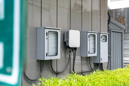
Reflective units ship in 4-wire conventional form (separate power and signal pairs) and in 2-wire intelligent form that draws power and signalling from the FACP detection loop, an architecture that is mechanically identical to a standard smoke detector on the same loop [S1]. System Sensor publishes the BEAM1224 (4-wire conventional) and the BEAM200 (2-wire intelligent) as the two integration patterns, with the 2-wire variant requiring a UL-listed compatible panel to set the loop current budget [S1].
End-to-end systems draw on the same FACP loop conventions, but each head needs its own loop address or conventional zone input, which doubles the address count on an addressable panel compared with a reflective pair covering the same volume [S2][S4]. For brownfield sites with limited addressable-loop spare capacity, the reflective 2-wire option is usually the lower-impact integration, while greenfield sites can plan the loop capacity around either topology. Cross-zone detection, where two beams must alarm together before the FACP activates suppression, is implemented identically in both, but the wiring cost is higher for end-to-end because the second head's loop drop is a full run back to the panel, not a short stub to a reflector on the same wall [S3][S5].
Selection Decision Matrix: Reflective vs End-to-End
On a criterion-by-criterion basis, the two topologies line up as follows for a typical 12 m clear-height industrial or commercial volume. Linear range: reflective 8–100 m, end-to-end up to 160 m, with both units typically spaced 15 m along the beam axis for detector-coverage calculations [S1][S4]. Cabling infrastructure: reflective needs a single drop (one power, one signal/loop), end-to-end needs two drops and, in some models, a separate wired power supply at the far end [S1][S3][S4]. Alignment effort: reflective is a single-head alignment against a passive reflector (one commissioning visit point), end-to-end is a coordinated two-head alignment with motorised adjusters on most modern units [S2][S4].
Best fit by use case: warehouses, distribution centres, and retail atria under 40 m wide with accessible ceiling structure point to reflective (System Sensor OSI-R-SS / BEAM1224 / BEAM200 family) [S1]. Aircraft hangars, covered stadiums, airport terminals, and cathedral-scale atria above 100 m clear span, or any installation where the far wall cannot be cabled to, point to reflective, while installations where the far wall is reachable and the path exceeds 100 m point to end-to-end (FireRay F3000 or equivalent) [S2][S4]. Maintenance access: reflective reduces lift-hire time by concentrating service at a single head, which matters in occupied buildings and tall spaces, but introduces a drift-compensation dependency on the reflector staying clean, so a six-monthly reflector wipe is the typical scheduled task [S3][S5].
Both topologies feed the same combustible-gas detector and cause-and-effect matrix logic on the FACP, so downstream suppression, smoke control, and emergency voice integration are unaffected by the choice. The next trackable signal for any specifier is the project-specific beam-path survey, which should record mounting-surface material (unstable steel versus masonry), expected structural deflection, ceiling height, and the longest unobstructed line-of-sight distance, because those four numbers alone force the topology decision before a model is even selected [S3][S5].
Background reading: Monolithic vs Multi-Segment Tiled Sputtering Targets for Large-Area Glass.