
Remote I/O installation becomes controllable when the engineer fixes the bus topology, power method, channel count, and signal type before mounting hardware.
The procedure covers cabinet and field modules using BACnet MS/TP and RS-485, and only a competent electrician is allowed to carry out the electrical installation [S2][S4][S5].
Define the module role and electrical boundaries
Remote I/O is not a single installation method: the Honeywell IO-16-REM-H supports 16 remotely located points through RS-485 multidrop, while the Azbil RJ-12 series uses BACnet MS/TP and can provide digital, pulse, relay, analog, and RTD functions [S4][S5]. Schneider Electric separates remote I/O heads, remote adapters, and remote drops into the 140 CRP 312 00, 140 CRA 312 00, and BMX CRA 312 .0 families [S3].
The IO-16-REM-H accepts eight universal inputs covering 0–10 Vdc, 4–20 mA, dry contacts, pulsing dry contacts, 0–100 kΩ resistance, and Type 3 thermistors. It also provides four Form A relay outputs rated to 24 Vac/dc at 0.5 A maximum and four 0–10 Vdc analog outputs for loads of 2.5 kΩ minimum or 4 mA drain maximum [S5]. These limits should be entered into the design schedule before field wiring begins.
Do not use a general-purpose module where human safety, transportation, aerospace, or controlled nuclear-area service applies unless the manufacturer explicitly approves the installation. The Azbil compact remote I/O module is compatible with BACnet MS/TP and can monitor operating and alarm states, turn equipment on or off, and measure data [S4].
Select the module against four decision criteria
A suitable remote I/O module must satisfy the required signal mix, communications protocol, electrical environment, and maintenance method. The comparison below separates these criteria because a module with enough channels can still be unsuitable if its bus, power, or output ratings do not match the field. [S4]
For a broader channel-count comparison, use 8 vs 16 vs 32 channel remote I/O modules to screen density before checking protocol and terminal details. A fieldbus gateway is relevant only when the selected module cannot terminate or translate the required fieldbus connection.
Plan power, grounding, and communications before mounting
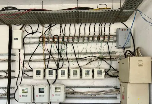
Power and communications are separate circuits even when they share a multipin connector. The IO-16-REM-H provides 16 remote I/O points, including eight universal inputs, four digital outputs, and four analog outputs, and can expand a WEBs-AX controller with an available RS-485 port [S5].
The Schneider guide identifies remote I/O head modules, remote I/O adapter modules, and remote I/O drops, while the IO-16-REM-H can expand a controller with an available RS-485 port [S3][S5]. These arrangements are not interchangeable.
Apply the module-specific grounding instructions before signal and power conductors are dressed into the enclosure. Keep the installation within the manufacturer's terminal, voltage, current, temperature, and environmental limits, and follow national and local electrical safety regulations. Only a competent electrician is allowed to carry out the electrical installation, and national and local electrical safety regulations must always be followed [S2].
Where the process includes Ethernet-connected modules, the industrial switch must meet the media, port-count, and environmental requirements of the network design. Do not substitute a generic Ethernet switch without confirming those conditions.
Mount the hardware and terminate field wiring
Mount the module in the planned orientation and location, using the manufacturer's fixing method and allowing the specified service clearance. For Schneider systems, identify whether the unit is the 140 CRP 312 00 head module, the 140 CRA 312 00 adapter, or the BMX CRA 312 .0 adapter before attaching it [S3].
Land each field conductor in the designated terminal, verify conductor gauge and insulation type against the module documentation, and tighten every applicable screw or push-in connection. Azbil's compact remote I/O module is compatible with BACnet MS/TP and supports digital I/O, totalizing pulse input, remote-control relay output, analog I/O, and RTD input [S4]. The I/O module installation sequence begins by pulling out the adapter cover and extending the red wiring clips before inserting the terminal conductors [S1].
Do not rely on the visible conductor position as proof of termination. Confirm the terminal assignment at both the module and field-device ends, then perform a continuity or insulation check appropriate to the circuit before energizing it. For sensor polarity, apply the PNP and NPN remote I/O wiring guide because digital input topology is a field-wiring decision, not a software setting.
Commission each signal in a controlled sequence
For the IO-16-REM-H, the documented sequence includes mounting, wiring, grounding, RS-485 communications, inputs, outputs, software representation, power-up, and initial checkout [S5]. Verify each input state at the terminal, compare it with the controller value, and operate each output through its intended controller command. The module accepts 0–10 Vdc, 4–20 mA, and Type 3 thermistor signals, so the configured engineering range and scaling must match the actual sensor [S5].
For BACnet MS/TP modules, verify the network address, baud rate, termination, and device object visibility before testing I/O. For proprietary or Ethernet systems, verify that the controller recognizes the correct head, adapter, or drop and that the configuration file matches the installed module [S3][S4]. Do not declare commissioning complete until field states, controller readings, alarms, and output responses agree.
Diagnose the dominant commissioning failure modes
A bus that fails to appear on the controller is usually an address, termination, cable, or topology issue rather than a failed I/O channel. Check that the physical node type matches the system design, including the distinction among the 140 CRP 312 00, 140 CRA 312 00, and BMX CRA 312 .0 families [S3]. Then verify addresses and termination one section at a time. Replace the module only after power, cabling, configuration, and controller compatibility have been ruled out.
An input that reads incorrect while other channels work usually points to the connected device, terminal assignment, signal type, or scaling. Test the field signal directly, then compare it with the configured range. For example, a 4–20 mA loop should not be interpreted as a 0–10 Vdc input, and a relay output carrying above 0.5 A violates the IO-16-REM-H rating rather than creating a recoverable configuration condition [S5].
An output that commands but does not actuate requires separation of controller logic, module output, field wiring, and load power. Verify the module channel before energizing the load, then check continuity and the load rating. If the output is within the documented 24 Vac/dc and 0.5 A maximum limits but fails, replace the module under the manufacturer procedure rather than increasing supply voltage or load beyond specification [S5].
Document handover and maintenance criteria

A completed installation record should identify the module model, serial number, location, protocol, bus address, firmware or configuration version, terminal schedule, power source, grounding method, and every tested channel. The Schneider guide, release dated 1 February 2022 and issued as version 14 under document reference S1A48978, defines the applicable Quantum EIO heads, adapters, and drops [S3].
Record the accepted state of each point, including a simulated or forced transition for outputs and a measured value for analog inputs. Keep the manufacturer's installation document at the panel or in the controlled maintenance file. The Honeywell installation instructions use document 95-7768-03 for the IO-16-REM-H, while Azbil document AB-7458 covers the RJ-12 family and BACnet MS/TP arrangement [S4][S5].
Re-test after any field-device replacement, controller configuration change, bus component change, or firmware update. If a field signal has drifted or an output no longer tracks its command, compare the measured value with the original acceptance record before replacing the module. Replace or escalate when the measured input, output load, supply, or bus value falls outside the manufacturer limits, because configuration changes cannot correct an electrical or capacity fault [S5].
Track two installation signals during handover: unresolved I/O channels and undocumented module changes. A module count that matches the approved schedule but lacks point-by-point test evidence is not an accepted installation.