
Remote I/O modules are classified by signal type, network protocol, and installation style. Remote I/O modules can offer different channel configurations, including an eight-output relay module, four-channel analog modules, and eight-channel digital modules, while Ethernet, RS-485, and IO-Link systems provide different expansion paths [S2][S3][S5].
The modules are intended for distributed plants, stand-alone data acquisition, and installations where field devices are too far from a PLC cabinet for practical local wiring. Selection starts with the required channel count, sensor or load type, communication protocol, cycle time, and environmental enclosure [S1][S7].
Core Remote I/O Classifications
Remote I/O is a group of input/output modules installed outside the main controller enclosure and connected through an industrial communications network. The controller exchanges process data with the modules, while the modules interface directly with sensors, switches, relays, valves, and other field devices [S4].
Digital and analog are the two primary functional classes. Digital modules process discrete signals, while analog modules handle continuously variable measurements or commands [S3]. A third practical grouping distinguishes protocol families, including Ethernet I/O in the Advantech ADAM-6000 series and RS-485 I/O in the ADAM-4000 series, with each family further divided by analog, digital, and mixed functions [S5].
Cabinet-based systems support flexible controller integration through description files, while field-installed systems place I/O close to process equipment and can use M12 push-pull connectors [S2]. The remote I/O module category therefore describes an electrical function, a communications role, and a physical architecture rather than one universal module design.
Digital, Analog, Relay, and Mixed Modules
Digital I/O modules are selected for binary field signals and relay outputs. Phoenix Contact lists a module with 8 floating digital outputs, solid-state relays per channel, electrical isolation between outputs, up to 6 A nominal current per output, and maximum dissipation of 1.3 W per output [S2].
That digital relay example also provides a useful performance boundary: the stated switching speed reaches 100 microseconds, which is materially faster than a mechanical relay arrangement and suitable for precision automation responses [S2]. In a motor-control application, the related comparison of relay and transistor outputs on modular remote I/O becomes relevant because output technology, load current, isolation, and switching life must be checked together.
Analog modules serve a different measurement class. The cited analog IO-Link box accepts as many as 4 sensors with M12 connectors and supports 2-wire, 3-wire, and 4-wire sensors. Its listed voltage ranges are 0 to 10 V, plus or minus 10 V, 0 to 5 V, and plus or minus 5 V [S2].
Mixed digital and analog modules are used when one physical area contains both signal types. The same product family also provides IO-Link I/O boxes for as many as 8 digital inputs and outputs through M8 connectors, with IP65, IP67, or IP69 protection options for field installation [S2].
Network and Field-Connection Options
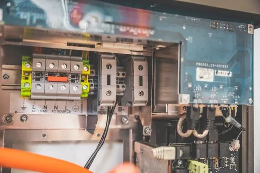
Ethernet and RS-485 define two practical network families for distributed I/O. Advantech classifies ADAM-6000 products as Ethernet I/O and ADAM-4000 products as RS-485 I/O, with both ranges subdivided into analog, digital, and mixed I/O categories [S5].
Fieldbus-connected systems add a protocol decision layer, with remote I/O systems offering Ethernet, RS-485, and IO-Link options and modules available for control-cabinet or field installation [S2]. The correct choice is the protocol supported by the controller and engineering platform, not a generic preference for Ethernet.
IO-Link serves as a point-to-point interface between a master and decentralized I/O. Phoenix Contact specifies IO-Link specification V1.1.4, an IO-Link Type A port, and an M12 connection from the master; the same specification appears for the 4-channel analog and 8-channel digital examples [S2]. For a controller with multiple industrial Ethernet ports or fieldbus lines, a fieldbus gateway may form part of the architecture, but it does not replace the selection of the correct I/O module.
Selection Criteria by Application
Remote I/O should be selected against four measurable criteria: signal compatibility, network compatibility, timing, and installation conditions. Signal matching requires confirming whether the field devices are digital, analog, or mixed and whether their voltage, current, wiring, and load requirements fall within the module specifications [S3][S7].
Network compatibility requires matching the module to the controller's supported interface, including Ethernet or RS-485 where those interfaces are supported [S2]. A module with the correct channel count is still unsuitable if its protocol, device description, or configuration method is unsupported [S2][S4].
Timing is driven by the process and the selected communication technology. Local I/O on a controller backplane normally provides lower latency than network-connected remote I/O, while remote placement reduces field cable length [S4]. For systems needing deterministic Ethernet motion or high-speed cyclic data, EtherCAT is a specific architecture, not a generic label for all Ethernet remote I/O.
Stand-alone acquisition changes the selection again. ADAM-6000 Ethernet I/O and ADAM-4000 RS-485 I/O are categorized specifically for stand-alone data acquisition and distributed I/O [S5]. In this case, the data-acquisition interface, protocol configuration, and channel mix matter more than PLC backplane compatibility.
Application Fit and Practical Limits
Remote I/O fits distributed machinery, long cable runs, and field devices spread across a plant. Placing modules near sensors and actuators reduces the amount of field wiring carried back to a central cabinet and allows the system to expand by adding network modules [S4][S6][S7].
It is a weaker fit where every millisecond of scan latency is critical and all devices can be reached from one cabinet. Local modules communicate through the controller's high-speed backplane and are physically close to the processor, so they retain an advantage in compact, time-sensitive installations [S4].
The main constraints are network latency, environmental exposure, topology and protocol dependencies, and field-wiring quality. Remote cabinets can be designed for moisture, vibration, and temperature exposure, but an installed module still needs a suitable enclosure and protection class. The cited M8 IO-Link boxes offer IP65, IP67, or IP69 ratings, while the selection guidance requires environmental conditions to be checked before purchase [S2][S7].
Reliability also depends on matching outputs to the load. Solid-state outputs in the cited 8-channel example switch resistive loads at 24 V, while output type, isolation, nominal current, thermal dissipation, and channel count must be considered before substitution [S2].
Specification Checklist for Buyers
A complete remote I/O specification requires at least 10 checked items: signal type, channel count, input or output voltage, output current, network protocol, controller compatibility, update or cycle time, connector format, protection rating, and expansion method [S2][S3][S7].
The comparison can be reduced to four decision rows. Digital modules win for discrete signals, analog modules for variable voltage or current signals, relay modules for switched loads, and IO-Link boxes for short point-to-point sensor connections [S2][S3]. Ethernet-based systems fit networked expansion and stand-alone acquisition, whereas RS-485 systems support a different distributed serial architecture; EtherCAT-based products suit cyclic fieldbus installations where the controller ecosystem already supports EtherCAT [S2][S5].
For configuration documents, the protocol-specific distinction between EDS and GSD or GSDML device-description files must be resolved before engineering approval. Phoenix Contact describes description-file integration as a central feature of remote I/O systems, so installation hardware, controller software, and device-description compatibility should be treated as one procurement package [S2].
The next verification step is a point-by-point I/O schedule that records each sensor or actuator, channel type, signal range, protocol, controller port, connector, protection requirement, and permissible cable arrangement. Every scheduled channel should then be checked against the module's published limits before the model is released for purchase.