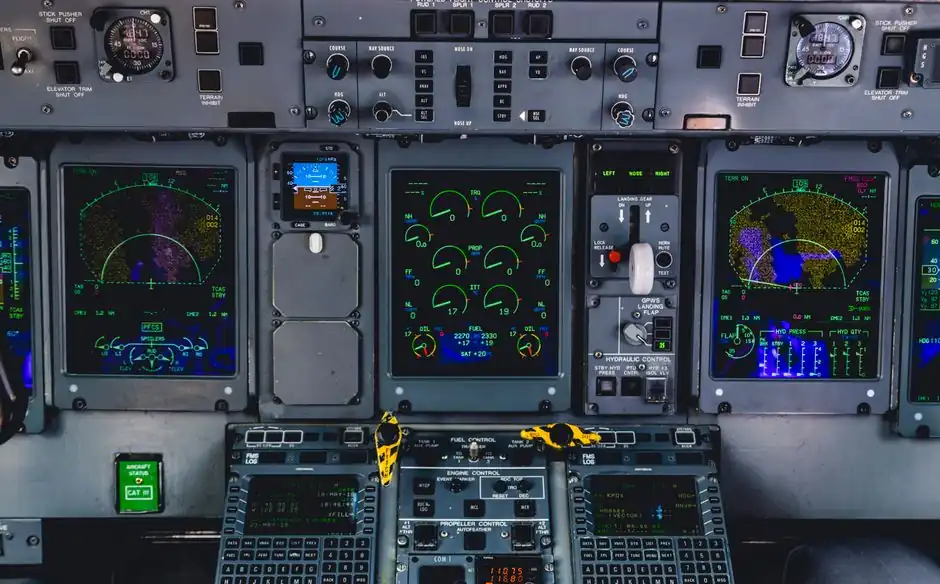
Projected capacitive and resistive touch are the two main industrial HMI technologies, with PCAP supporting multi-touch and resistive systems accepting thick gloves [S4][S6].
The choice also depends on installation form: standard panels, web panels, outdoor units, maritime units, and headless HMIs serve different operating environments [S2].
Hardware classification and operating principle
An HMI touch panel combines 5 functional elements: a touch sensor layer, display panel, HMI software, controller or processor, and enclosure [S5]. The sensor converts physical contact into electrical signals, while the display presents status, readings, controls, and alarms; the software and processor connect those functions to the controlled machine [S5].
For a deeper view of the complete assembly, including the sensor, display, processing, software, and protective housing, see HMI touch panel construction and core components. Touch technology alone does not determine suitability, because panel size, enclosure protection, installation method, lighting, operator gloves, and controller connectivity shape the final specification [S2][S4][S5].
PCAP and resistive touch compared
Projected capacitive touch detects light contact, supports multi-touch, and normally places the sensor behind cover glass; resistive touch requires pressure, is usually single-touch, and commonly uses a flexible PET layer that can be cut or punctured [S4].
PCAP is the stronger default for new general-purpose industrial HMIs, especially where multi-touch, sealed glass, and glove operation are required. Resistive technology remains defensible when operators wear thick gloves, conductive gloves would create false inputs, the budget is constrained, or legacy equipment depends on pressure-based input [S4][S6]. Resistive construction is also available in 4-wire, 5-wire, and 8-wire variants [S6].
Large-format, marine, and specialized constructions
Infrared touch typically serves large screens, including 55–100-inch or larger formats, while optical imaging supports very large displays, including 100-inch-plus units; both support multi-touch [S4]. Infrared systems require an emitter and receiver frame, whereas optical imaging uses cameras and may increase bezel or corner depth [S4].
Surface acoustic wave touch uses hard glass and provides high optical clarity, but standard implementations are single-touch and require a soft object or rubber stylus; water and dirt interfere with detection, restricting it mainly to clean indoor terminals [S4]. A separate outdoor-readable class addresses visibility rather than sensor physics, while maritime HMIs address marine installations; standard, web, and headless classes cover general, browser-based, and remote or distributed operation respectively [S2].
Panel form factors and operator functions
Standard HMIs suit machine-level monitoring and direct operator control, web-panel HMIs serve browser-based access, and headless HMIs move visualization to another screen or remote endpoint [S2][S3]. Siemens offers SIMATIC HMI Panels as part of its control and programming systems products.
Typical industrial HMIs include standard panels, headless panels, Windows HMIs, Wi-Fi-enabled HMIs, high-brightness HMIs, RFID HMIs, gateway HMIs, web HMIs, and units with remote I/O; one catalog category also lists 21.5-inch capacitive-touch HMIs and compares models including cMT2078X, cMT2108x2, and HMI5070Bv3 [S3]. These are product-family variations, not one universal classification system.
A graphical HMI presents operating data and controls for automated systems [S7]. When the display must serve as a broader supervisory interface rather than a local station, SCADA software becomes part of the architecture, but it does not replace the panel, sensor, controller, or enclosure.
Selection criteria for industrial installations
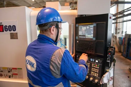
The first selection decision is the input environment: use PCAP for multi-touch and sealed-front operation, resistive for pressure-based input with thick non-conductive gloves, infrared for large-format multi-touch, optical imaging for very large controlled interiors, and SAW only where clean indoor conditions and single-touch are acceptable [S4].
The second decision is installation exposure. Outdoor-readable HMIs address visibility in harsh light, maritime HMIs address marine use, and protected enclosures address dust and water exposure [S2][S5]. Industrial displays may use high-brightness panels, and suitable units can be offered with IP66 or IP69K protection, extended temperature capability, stainless-steel construction, or optical bonding [S3].
The third decision is system architecture. A local panel should communicate with the controller or PLC through the required industrial protocol; Modbus, EtherNet/IP, and PROFINET are examples of protocols handled by HMI software [S5]. For mobile or distributed operators, a web panel or headless HMI shifts display access toward a browser or remote terminal rather than placing every interaction point at the machine [S2][S3].
Limits, failure modes, and intended users
Resistive touch has a damage-prone exposed PET layer, while capacitive touch can misread water unless rejection is tuned [S4]. Infrared systems can produce false touches when the frame is contaminated; direct sun and component temperature ratings can affect infrared performance. Optical imaging can be disrupted by strong ambient light, reflective edges, or obscured cameras [S4].
SAW is unsuitable where dirt or water is expected because both interfere with detection [S4]. A headless HMI is also the wrong choice when operators require a guaranteed local display and direct touch interface at the equipment, while a fixed touch panel is less suitable when access must move among multiple user locations. The appropriate industrial display must therefore match both human interaction and physical installation.
Procurement specification and verification
Specify an HMI touch panel by touch technology, resistive wiring where applicable, multi-touch capability, screen size, glove and stylus requirements, display brightness, enclosure rating, operating environment, communications protocol, and available I/O [S3][S4][S5][S6]. For resistive products, record whether the design requires 4-wire, 5-wire, or 8-wire construction [S6].
For large-format systems, record display size, mounting depth, ambient light, contamination exposure, and multi-touch count rather than applying the same selection logic used for a 7-inch machine panel [S4]. The documented operating requirements of the chosen model, including enclosure ratings and temperature limits, should then be checked against the installation site [S3].
A workable procurement record should identify the panel form, sensor type, display specification, enclosure, controller interface, software environment, and operator input condition; matching those 7 items to the installation site gives procurement and engineering a traceable basis for comparison.