
A retaining ring can retain a component on a thin-walled hollow shaft, but the groove, not the ring, often limits allowable thrust capacity.
External shaft rings act as removable axial shoulders, while shallow hoop-style rings suit thin-wall tubing; both require load calculations based on groove geometry and material yield strength.
Can a retaining ring work on a thin-walled hollow shaft?
Yes, provided the shaft has a mechanically sound external groove and the ring is sized for that groove rather than for the outside diameter alone. External retaining rings fit into a machined shaft groove and prevent axial movement of the retained component, while internal rings fit into a housing groove [S2][S7].
The principal constraint is the hollow or thin-wall section surrounding the groove. A ring can place a substantial axial load into the groove wall without that wall having sufficient section thickness to carry the resulting stress. For hoop-style rings, the shaft or housing, rather than the ring, usually limits load capacity [S4].
Hoop-style retaining rings are particularly suitable for cylinders and thin-wall tubing because their thin radial section permits a shallower groove with limited projection beyond the shaft [S3][S4].
Groove strength determines the usable thrust load
The groove must be treated as a load-carrying structural feature. Rotor Clip states that groove capacity becomes limiting when it is lower than ring capacity, especially when the groove is cut into softer material [S1]. When a ring is seated in a groove cut in softer material, groove capacity can become the limiting factor in the assembly [S1].
Two practical details matter. Second, the retained part should bear against a reasonably square face and be concentric with the shaft; radial play must be treated as an equivalent chamfer when evaluating the ring [S1].
External shaft rings versus hoop-style options

The main comparison is between a conventional external retaining ring and a low-profile hoop-style ring. Both can form an axial shoulder on a hollow shaft, but they differ in groove depth, radial space, installation method, and the way the assembly should be evaluated. [S5]
For conventional grooved rings, ring and groove capacities should be checked separately. If the shaft or housing material and groove geometry produce a lower allowable load, that groove capacity governs the assembly [S1]. This distinction is critical for hollow shafts, because the section below the groove may fail before either published ring capacity is reached.
Edge margin and hollow-wall thickness need separate checks
A groove too close to the end of a hollow shaft loses load capacity through edge effects. For grooved rings, an edge-margin ratio of y/d≥3 allows the groove to withstand the maximum thrust listed for that ring type and size [S1].
The worked example uses an SH-50 external ring on cold-rolled steel with a 0.016 in. groove depth and a recommended 0.048 in. edge margin, giving y/d=3 and a ring capacity of 550 lb [S1]. If the edge margin is reduced to 0.008 in., so y/d=1.5, the calculated groove capacity falls to 256.9 lb [S1].
Wall thickness must also be checked independently. The edge-margin calculation addresses material left beyond the groove, while a hollow shaft may lose strength through the bore below it. Neither a catalog thrust value nor an edge-margin ratio alone proves that the shaft wall is adequate.
Ring construction and installation affect suitability
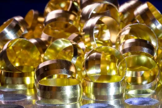
Spiral retaining rings are generally intended for low-thrust applications [S6].
Constant-section or hoop-style rings suit compact assemblies and thin-wall tubing, but their shallow grooves make groove-wall dimensions and corner geometry critical [S4]. Retaining rings are used to fasten assemblies on shafts or in housings and bores [S5].
Applications where the hollow-shaft design is appropriate
Thin-walled hollow shafts are plausible in lightweight rollers, actuator housings, pulley or hub assemblies, and tubular mechanisms where axial travel must be limited without adding a full shoulder. The retaining ring creates a removable shoulder that can reduce assembly length compared with a machined shoulder or threaded fastener [S5].
Hoop-style rings are the better starting point when radial space is restricted and the groove can be machined with controlled depth and corner radii [S3][S4]. A conventional external ring remains viable when its groove depth fits the shaft wall and its calculated ring and groove capacities both exceed the applied axial load [S1].
The design is not appropriate when the hollow section cannot support a concentric groove, when edge distance is inadequate, or when dynamic shock, high temperature, corrosion, or repeated removal changes the load and material conditions. For bearing arrangements, the ring must accommodate the bearing's axial thrust rather than merely prevent slow migration [S5].
Specification checklist for a manufacturable hollow-shaft groove

Specify the shaft outside diameter, inside diameter or minimum wall thickness, groove diameter, groove width, groove depth, and edge margin before selecting a catalog ring. A practical manufacturer drawing should also state groove corner radii, surface finish, shaft material, heat treatment, and the retained component's face geometry. [S1]
Use the selected ring manufacturer's capacity chart as one input, not as a blanket approval. The final assembly requires four checks: ring material and geometry, groove-wall capacity, edge-margin capacity, and minimum hollow-wall section strength [S1][S4].
Material selection must match the environment. Smalley lists standard retaining-ring sizes from 0.25 to 16 in. or 6 to 400 mm in carbon and stainless steel, with over 6,000 standard rings and 30 configurations [S2][S3]. This size range does not by itself establish suitability for a thin hollow wall.
For further application-specific criteria, the retaining-ring selection guide for material-handling conveyors and drives covers load environment, groove controls, and installation constraints that also affect thin-wall shafts.
The traceable approval point is the released groove drawing with applied axial load, shaft material and yield strength, measured wall thickness, calculated groove capacity, and the selected ring's catalog capacity. If any one of those values changes, the thrust check should be repeated.