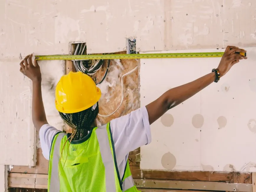
Commercial HVAC installation is one of the highest-leverage use cases for robotic total stations: hanger and trapeze layouts on a 5,000 m² mechanical room involve thousands of points, and a 2 mm to 3 mm angular error at the instrument compounds into centimetre-scale duct misalignment at the far end of a run [S2].
The two Leica iCON robotic models most often specified for HVAC work in 2026 are the iCR70 (1″ angular accuracy, ~1,000 m reflectorless range) and the iCR80 (1″ / 2″ options, up to 3,500 m with a single prism), both designed for one-person operation and BIM/IFC file import [S2]. Designers also need to remember that ACCA Manual S caps sensible cooling equipment selection at 115% of Manual J sensible load and 125% of total cooling load, so layout precision directly drives whether the installed tonnage actually lands inside that window [S3].
Why Robotic Total Stations Win on HVAC MEP Coordination
Mechanical, electrical, and plumbing (MEP) coordination is where HVAC layout loses the most time: duct, pipe, conduit, and sprinkler runs compete for the same ceiling plenum, and a hanger located 30 mm off clashes with a fire-protection main on shop drawing review. A robotic total station reads BIM/IFC files directly through Leica iCON build software, so the field crew lays out the model that was coordinated in the office rather than a re-drawn 2D version [S2]. Robotic tracking of a prism on a pole lets the same operator set the instrument, walk to the point, and mark it without a second crew member, which design-build HVAC contractors report as the single largest productivity gain on commercial jobs [S1][S2].
For HVAC-specific work, three workflows dominate: (1) anchor-bolt and equipment-base layout for air-handling units (AHUs) and chillers, where bolt pattern tolerance is typically ±3 mm; (2) overhead hanger and trapeze layout for rectangular duct, where plenum congestion means a 10 mm error is the difference between a clean install and a field rework; and (3) as-built verification against the coordinated 3D model before ceiling close-up, where the cost of finding a clash after drywall is roughly 10x the cost of finding it beforehand [S1][S2]. Glassman Corporation, a US design-build HVAC contractor, uses total-station layout together with 3-D CAD virtual build to "virtually build mechanical systems" before fabrication, eliminating field mistakes on ductwork, piping, and plumbing [S1].
Selection Criteria: Accuracy, Range, and BIM Integration
Three spec criteria drive the right model for an HVAC project: angular accuracy, range class, and software/BIM integration. Robotic total stations in the iCON family carry angular accuracy from 1″ to 5″; for HVAC MEP layout in commercial buildings, 2″ to 5″ is the practical sweet spot because bolt-pattern tolerances (typically ±3 mm) and hanger-pattern tolerances (typically ±6 mm) do not justify 1″ surveying-grade pricing [S2]. Range comes in two flavours: reflectorless (useful for indoor ceilings and unfinished walls, typically 500 m to 1,000 m on the iCR70) and prism (outdoor and long mechanical-room runs, up to 3,500 m on the iCR80) [S2].
BIM integration is the third pillar: Leica iCON build runs on a tablet or field controller, imports 2D CAD and full 3D IFC files directly, and pushes layout data back to the office through the ConX cloud platform, so the as-built point cloud is compared against the design model in near real time [S2]. HVAC crews that are still working from 2D PDFs are essentially trading the 10x rework cost of post-close-up clashes for the much smaller cost of a robotic layout pass before close-up, which is the core economic argument for going robotic on any commercial HVAC job [S1].
Comparison: iCR70 vs iCR80 vs Manual Total Station vs Laser Meter
Lining the four main options up against the criteria that matter to an HVAC installer, the picture is straightforward. The Leica iCR80 sits at the top for angular accuracy (1″ option), prism range (up to 3,500 m), and full BIM/IFC integration, at the highest unit cost, and is the right pick for hospitals, data centres, and large mechanical rooms with 5,000+ layout points [S2]. The iCR70 drops to 1,000 m reflectorless and 2″ to 5″ accuracy, hits a much lower price point, and is the workhorse for typical 1,000 m² to 5,000 m² commercial HVAC jobs. Manual total stations (no motorised tracking) require a two-person crew and offer no direct BIM file import, so they only make sense for small tenant-fit-out jobs under 200 m² where the layout crew is already a two-person survey team. Laser distance meters cap out at ~200 m, ±1.5 mm accuracy, and are restricted to single-point measurements with no model integration; they are the right tool for residential service calls and rough take-offs, not for coordinated MEP layout [S2].
Specifying beyond the iCR80 to surveying-grade total stations (0.5″ accuracy) rarely makes sense for HVAC, because the layout tolerance of the equipment itself (bolt patterns, duct flanges, hanger rods) is coarser than the instrument can resolve; you pay for accuracy the system downstream cannot use [S2]. On the opposite end, a tape measure and chalk line should not be used for any commercial HVAC work where a coordinated BIM model exists, because the rework cost from clashes after ceiling close-up is the single largest controllable cost on most mechanical installations [S1].
Use Cases That Fit and Use Cases That Do Not
Robotic total station layout is a clear win for: commercial HVAC design-build projects (typically 1,000 m² and up); MEP coordination on healthcare, data-centre, and laboratory projects where as-built verification against BIM is contractually required; high-bay industrial HVAC where overhead hanger runs exceed 50 m and reflectorless range is needed; and campus-scale chilled-water and steam distribution where prism range past 1,000 m is the constraint [S1][S2]. It is a poor fit for: residential service and replacement work (a Manual J load calculation plus a laser meter is sufficient); small tenant fit-outs under 200 m² with no BIM model; and outdoor-only surveying where a GPS/GNSS rover is faster and cheaper. For a fuller grounding in how the total station instrument class compares to other layout tools, the spec fundamentals are worth a read before committing budget.
Two failure modes are worth flagging up front. First, on reflective surfaces (stainless duct, polished pipe, glazed tile), reflectorless EDM can give false returns, so always carry spare prisms and use prism mode for any final bolt-pattern mark. Second, BIM/IFC files exported from Revit or ArchiCAD must be checked for unit consistency (mm vs m) and shared-coordinate origin before going to the field; a coordinate-frame mismatch is the single most common reason a robotic layout pass goes wrong on day one [S2].
Linking Layout Precision to ACCA Manual J / Manual S Sizing
Layout precision and equipment sizing are linked more tightly than most HVAC crews realise. ACCA Manual J produces the load in BTU/h (1 ton of refrigeration = 12,000 BTU/h), and ACCA Manual S then caps the selected equipment at 115% of the calculated sensible cooling load and 125% of the total cooling load; these are upper bounds, not design targets, and an oversized unit short-cycles, fails to dehumidify, and wears out prematurely [S3]. When the field layout of supply diffusers, return grilles, and equipment bases is wrong by even 30 mm, the resulting airflow imbalance can pull the operating sensible heat ratio outside the band the manufacturer rated, which effectively turns a properly sized system into an oversized one in practice [S3].
Design temperatures for Manual J are drawn from the ASHRAE Handbook of Fundamentals, with summer design at the 1% exceedance condition (the temperature exceeded only 1% of hours annually) and winter design typically at the 99th percentile cold temperature for the location [S3]. Infiltration inputs to Manual J come from blower-door ACH50 testing or equivalent estimates, and ventilation inputs come from ASHRAE 62.2-2022 (residential) or 62.1 (commercial); all of these feed into the load that the equipment must meet, which is in turn sensitive to where the equipment and ductwork are physically placed on the project [S3]. Bottom line: tight layout, sized-right equipment, and verified as-builts are the same engineering decision viewed from three different angles, and the robotic total station is the instrument that ties them together on a commercial HVAC job.
When a Robotic Total Station Is the Wrong Tool
A robotic total station is the wrong tool when any of the following are true: the project is residential or light-commercial under 200 m² with no coordinated BIM model; the layout tolerance is dominated by the fabrication of duct and pipe (where shop-fab jigs and laser levels are the right tool); the crew has no tablet/field-controller workflow and no IFC file pipeline; or the budget per project cannot absorb the unit cost of the instrument amortised over jobs. In these cases, a flow meter or laser distance meter is the right pick for the take-off and rough layout, and the budget is better spent on Manual J software and a blower-door test than on a robotic total station that will sit in the van [S2][S3]. For a side-by-side look at how the same instrument class performs on a different trade, the total station spec map for masonry layout is a useful cross-check on tolerance, range, and crew-size assumptions. Where the work is structural steel rather than mechanical, the criteria shift again, as laid out in the total station spec map for steel construction.
Track the following two signals over the next 6 to 12 months before committing capital: (1) ACCA and ASHRAE guidance updates to Manual J, Manual S, and ASHRAE 62.1/62.2 ventilation inputs that change how layout tolerance feeds into the sizing calculation, and (2) robotic total station price points on the iCR70 class, which have been trending down as 1″-accurate MEMS IMUs enter the construction-layout market and put pressure on traditional servo-driven instruments.
Spec-level background on the components involved: weather station.