Robotic total stations selected for electrical installation work in 2026 are almost exclusively MEP-layout class instruments with 1 to 3 arcsecond angular accuracy, green or red beam laser visibility, and direct export to BIM/CAD field-layout software, rather than survey-grade optics [S2].
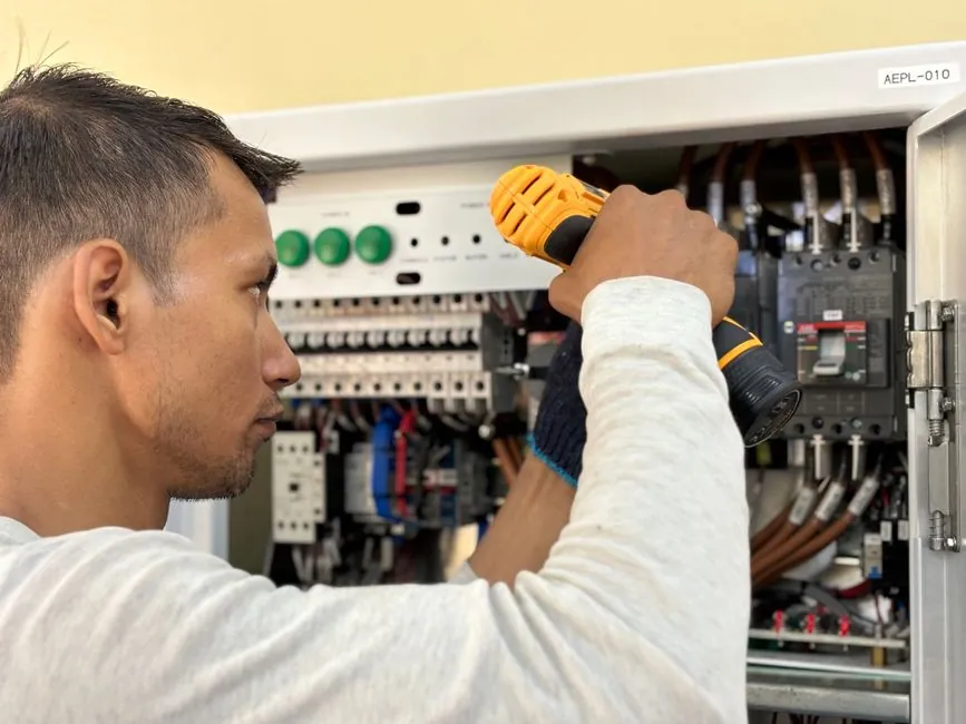
Electrical scope here means interior rough-in for conduit, cable tray, transformer pads, busway hangers, panel back-boxes, lighting layouts, substation equipment foundations, and EV charger locations, where the crew needs to set out hundreds of hangers or embed points to a few millimetres, not run traverse networks [S1][S2].
What "Electrical Installation" Actually Means in Total Station Work
Electrical installation is one of three main load cases the MEP layout total station is built for, alongside mechanical (HVAC duct, pipe, equipment pads) and plumbing (drainage, sanitary, medical gas) [S2]. The Trimble RTS series is purpose-built for this triad, with field software driving the robotic lock and reflectorless measurement cycles [S2].
Typical field deliverables include points for conduit penetrations, equipment anchor bolts, lighting fixture centres, busway support points, cable tray bends, and ground-grid test links, where horizontal tolerance is generally 5 mm to 10 mm and vertical tolerance is often 3 mm to 5 mm over a single room or bay [S1][S4]. At substation scale, primary equipment foundations (breaker pads, transformer rails, gantry columns) require the same robotic workflow but with longer sight distances, 50 m to 150 m, and tighter 3 mm relative tolerance between matched anchor groups [S4].
Accuracy Class and Sensor Configuration That Matter
MEP-layout total stations are most commonly specified in the 1 to 5 arcsecond angular class, with distance accuracy around 2 mm + 2 ppm in prism mode and roughly 3 mm + 2 ppm reflectorless, which is sufficient for almost all electrical anchor and embed work [S2]. The 0.5 arcsecond tier (S9-class) is reserved for monitoring and deformation surveys, not layout, and is overkill for conduit or panel layout [S2].
The relevant spec stack to lock down before purchase is: angular accuracy in arcseconds (1", 2", 3", 5"), distance accuracy in mm + ppm for both prism and reflectorless, range on a single prism in metres, reflectorless range to a typical concrete or steel target, internal compensator type (dual-axis liquid), and EDM update rate in Hz [S2]. Battery hot-swap, operating temperature window, and IP rating also belong on the same one-page check, because electrical rooms and outdoor substation yards span -20 to +50 °C ambient in many regions [S2].
Green Beam vs Red Beam: The Visibility Decision
Green beam (532 nm class) lasers are roughly four to six times more visible to the human eye than red (635 nm class) at the same output power, which directly determines how fast a layout crew can pick up a point on a bright jobsite or in a sun-lit interior with high-bay glazing [S2]. The top RTS 873 ships with a green auto-focusing layout laser for this reason, and is the default pick for outdoor substation and high-bay industrial electrical work [S2].
Red beam (RTS 773, RTS 673) remains adequate for interior buildouts under normal overhead lighting, and saves on cost and on operator eye fatigue during long indoor shifts, but the operator can lose the dot against a white conduit on a bright skylight or against a galvanised cable tray in direct sun [S2]. The trade-off is essentially: spend the money on green if the work is at least partly outdoor or under daylight penetration, save the money on red if it is enclosed interior from the first hanger to the last termination [S2].
Software Stack: Field Layout, BIM, and the Trimble Vision Question
MEP layout total stations are not used as standalone angle-and-distance boxes; they are driven by field layout software that imports Revit, IFC, or DWG models, generates point lists, and runs the robotic lock-and-measure cycle automatically [S2]. Without that software hand-off, the total station collapses to a slow theodolite, because the layout speed gain comes from model-to-field automation, not from the optics alone [S2].
Trimble Vision, the live video overlay on the higher-tier RTS 873, lets the operator aim and QA points remotely through the camera, which matters when the target is a live switchgear bus or a panel the operator cannot stand near, and it is the main differentiator between the 873 and the 773 [S2]. A track light below the lens on the 673 helps the rodman find the prism in busy MEP ceilings, but it does not replace the camera overlay for remote aiming [S2].
Comparison: RTS 873 vs RTS 773 vs RTS 673 vs S-Series for Electrical Work
On a four-criterion comparison for electrical installation work, the picture is fairly clean. Criterion 1, beam visibility in mixed lighting: RTS 873 green beam wins, RTS 773 and 673 red beam acceptable only indoors. Criterion 2, remote aiming on energised gear: RTS 873 with Vision, then RTS 773 with Vision, then RTS 673 with track light only. Criterion 3, accuracy headroom: 1 to 3 arcseconds across all three is more than enough for electrical layout, so the S9 at 0.5" is wasted spend. Criterion 4, software: all three are paired with the same MEP field layout package, so no real cost difference there [S2].
The S Series (S5, S7, S9) is built around Trimble Access for surveying workflows and is the wrong tool for electrical MEP layout, even though the optics are stronger, because the field software, the prism-tracking cadence, and the cost are all aimed at traverse and monitoring work, not at importing a Revit electrical model and stepping through 800 hanger points in a day [S2]. Picking an S7 over an RTS 773 for electrical installation is the most common spec mistake and usually shows up as a slow layout crew, not as a bad point [S2].
Site Calibration, Compensator Checks, and When to Send It Out
Field calibration for an MEP total station is a daily five-minute routine, not an annual service: level the instrument, run the dual-axis compensator check, sight a known backsight and foresight to confirm horizontal and vertical index, then measure to a fixed prism at a fixed distance and compare against the stored baseline [S3]. A deviation of more than 3 mm at 30 m on the prism baseline, or a compensator warning on power-up, is the trigger to pull the unit off the job, not to compensate in the software [S3].
Three failure modes end a field session and route the instrument to a service centre: persistent compensator error after a warm reset, angular residuals that walk by more than the spec arcsecond value over a 10-minute observation, and erratic distance readings on a known prism (jumping more than 5 mm between successive shots under stable conditions) [S3]. Drop events, water ingress, and long storage in a hot vehicle are the three root causes behind most of these failures on electrical jobs, and any of them should land the instrument on the bench regardless of how new it is [S3].
Regulatory and Standards Context Around the Layout
Total station selection for electrical work is rarely driven by the instrument's own certification, because the standard chain is upstream: the layout coordinates feed into an electrical installation designed to IEC 60364, and that design sets the physical tolerances the total station must hit, not the other way around [S5]. In a New York City context, the same layout points are also tied to electrical filings under DOB NOW: Build, where permits are valid for a maximum of 12 months and need a $130 renewal, a workflow point that does not change the instrument spec but does change how long the unit must stay calibrated on a multi-phase project [S1].
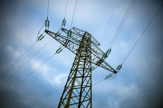
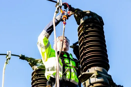
At substation scale, the design package is governed by primary-design practice for equipment siting, grounding, and clearances, and the total station becomes a high-stakes tool because anchor group tolerances on transformer rails and breaker pads feed directly into bus and connector fit-up downstream [S4]. The same total station works for both interior and substation work; the difference is in QA cadence, prism baseline checks at the start of every shift, and the use of redundant control points across the larger sight distances [S3][S4].
Spec Window and Shortlist Recommendation
For most electrical installation work in 2026, the spec window is: 1 to 3 arcsecond angular accuracy, 2 mm + 2 ppm prism distance accuracy, reflectorless range at least 200 m on a concrete target, dual-axis compensator, green beam for any outdoor or daylit work, MEP field layout software with direct Revit/IFC import, IP54 or better, and a battery system that supports hot-swap on a single shift [S2]. The RTS 873 sits at the top of that shortlist for substation and high-bay work; the RTS 773 is the default for interior commercial electrical; the RTS 673 is the right call only on cost-driven interior-only scopes where the operator can stand near every point [S2].
Two trackable signals to watch for the rest of 2026: tighter BIM-to-field interoperability requirements being folded into IEC 60364-aligned installation guides, which will push layout software features up the buying criteria, and growing EV-charger rollout programmes, which will create steady interior-and-exterior MEP layout work that the RTS class was designed for [S1][S5]. For a parallel spec walk-through of total station use on road maintenance and on masonry layout, see the Total Station Selection for Road Maintenance: 2026 Spec Map and the Total Station Spec Map for Masonry Layout: 2026 Selection Guide guides. For a wider grounding in instrument categories used across site engineering, the total station reference page is a useful baseline.
Spec-level background on the components involved: weather station, and eye wash station.