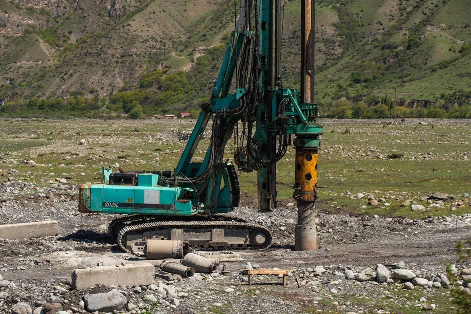
A rotary drilling rig is not one product but a family spanning roughly an order of magnitude in hole diameter and mass: the RTDrill RTD28 down-the-hole unit weighs 24,500 kg and drills 95–152 mm holes at 23 bar (333 PSI) using a CAT C13 engine [S3], while SANY's SR365R-W10 piling rig drills 2,200–2,500 mm diameters to 65–100 m depth [S1]. Installation logic therefore forks by class: light DTH skids, mid-range crawler augers, and heavy piling rigs each demand a different transport footprint, mast erection sequence, and commissioning test envelope.
This guide frames the installation workflow as a decision tree — site assessment, class selection, transport/assembly, mast raise, kelly-bar verification, and acceptance test — anchored to the concrete specs of units currently shipping in 2026, plus a checklist of failure modes that surface in the first 200 operating hours [S4]. For a primer on how the rotating drive head and crowd system work mechanically, see the rotary drilling rig encyclopedia entry.
Match Rig Class to Hole Envelope Before Mobilising
The single most expensive installation mistake is delivering a piling-class crawler to a 120 mm blast-hole job, or vice versa — under-rigged crowds stall, over-rigged carriers sink soft pads. Three reference classes bracket the field: light DTH rigs in the 24,000–30,000 kg range handling 95–152 mm diameters with 287–309 kW (390–420 hp) power packs and 20.6 m³/min (727 CFM) air [S3]; mid-range crawler augers such as the SANY SR205-C10, diesel-driven, remote-controlled, drilling 1,800 mm diameter to 51–64 m depth for civil-engineering foundations [S2]; and heavy piling rigs like the SR365R-W10, delivering 2,200–2,500 mm diameters to 65–100 m depth with high crowd force and fast main-hoist line speed for hard formations [S1].
Selection must lock in four numbers before mobilisation: target hole diameter (mm), target depth (m), required torque (kN·m) and crowd force (kN), and formation class (soft soil, mixed face, weathered rock, hard rock). A class mismatch is rarely fixable on site without a derig-and-re-mobilise event that burns two to three working days.
Site Survey, Transport Plan, and Pad Preparation
Ground-bearing pressure drives pad design. A 24,500 kg DTH rig on outriggers exerts roughly 60–75 kPa on a 4 m × 4 m timber mat, whereas a heavy piling rig (typically 70,000–100,000 kg in working trim) demands reinforced bog mats or a stone pad rated for 150 kPa+ sustained loading [S4]. Soft clay sites with CBR below 3% require either a geotextile + crushed-stone base or full crane-assisted mat-laying; ignoring this path turns the first mast raise into an inclination event.
Transport dimensions are the second gating item. A crawler piling rig in shipping configuration generally falls inside a 12 m × 3.2 m × 3.4 m envelope but exceeds 60 tonnes gross — over-width/over-mass permits are mandatory in most jurisdictions, and escort-vehicle planning must include route survey for bridge clearances and roundabouts. Site access must allow a low-loader turn radius of at least 18 m for heavy piling class. Offload requires a hydraulic ramp or a 100-tonne crane; underestimating crane reach is the most common cause of the first-day delay.
Mast Erection and Kelly-Bar Pre-Run
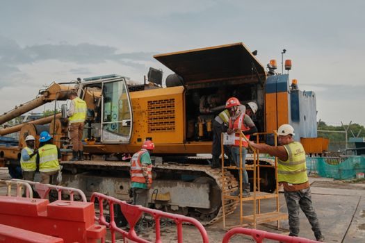
Mast raise sequence is the only step that physically puts personnel within the failure zone, so rigging-pin verification and hoist-line inspection precede any human step near the under-mast area. A 2018 structural study of main-winch mounting position on rotary mast strength confirmed that axial force and bending moment distribution in the mast shifts measurably when the winch is relocated from platform to lower-mast position, reinforcing the rule that re-rigging a winch without re-running the OEM structural check is a documented overstress path [S9].
For a heavy piling rig, kelly-bar sections must be torque-passed and telescoped dry before any auger is attached — each section's female socket inspected for galling, each drive key confirmed for full engagement, and the bar rotated at low RPM through full extension to confirm smooth telescoping. Crowd force should be limited to 30% of nameplate during the dry run. A kelly-bar that telescopes dry but stalls under load almost always has contaminated or under-greased drive splines; cleaning and re-greasing is the corrective action, replacement is the only option once drive keys have spalled.
Engine, Hydraulics, and Electrical Commissioning
Hydraulic commissioning follows a staged ramp: cold start, idle at 800 RPM for 10 minutes to circulate oil through all return-line filters, then incremental RPM steps (1,200 / 1,500 / 1,800) holding five minutes at each step while monitoring filter differential-pressure gauges. The RTD28's CAT C13 Tier III / Tier IVf / Tier V engine runs at 1,800 RPM for nameplate 287–309 kW output [S3], and the same RPM window applies to most modern diesel piling rigs in the 200–360 kW bracket.
Hydraulic-hose pre-tension and routing is the next most common install failure: a hose that is too tight when the mast is vertical will stretch or kink when the mast is laid for transport, leading to a burst on the next raise. Acceptance: every hose shows visible slack at full mast angle and at full transport angle, and every coupling shows torque-paint witness marks. Electrical commissioning should include a load test on the cab HVAC, the rotary-head encoder feedback circuit, and any optional remote-control link — the SR205-C10 and SR365R-W10 both carry remote-control options [S1][S2], and a radio-link drop-out during the first borehole is a known commissioning-time failure [S4].
Acceptance Test: Borehole Verticality, Penetration Rate, and Instrument Calibration
Acceptance is not "the rig spins up" — it is a documented pass on verticality, rate of penetration (ROP), and instrument calibration against a reference borehole. For piling class, verticality tolerance is generally 1:200 (0.5° over the full depth) verified with an inclinometer or the rig's onboard verticality system; deviation beyond this is reject-and-redrill, not adjust-and-continue. For DTH class, the acceptance test focuses on hammer pressure stability at 23 bar and 20.6 m³/min airflow [S3] — a drift in either parameter beyond ±5% indicates a compressor or regulator issue upstream of the rig.
Instrument calibration is the third leg: rotary encoders, depth counters, and crowd-pressure transducers must be cross-checked against a manual tape and a calibrated load cell. The 2018 study on drilling-parameter formation identification showed that real-time detection of direct parameters (rotary speed, torque, crowd force, penetration rate) and derived parameters (specific energy) is only as reliable as the sensor stack feeding the data acquisition system [S8].
First-Shift Failure Modes and When to Escalate
Five failure modes surface in the first 200 hours, and each has a defined corrective action: (1) hydraulic-filter collapse — replace filter, sample oil, escalate to OEM if metallic debris exceeds 50 ppm; (2) kelly-bar drive-key wear — replace keys, inspect sockets, escalate if female socket ovality exceeds 0.5 mm; (3) rotary-head gearbox overheating — check oil level, cooler fan operation, and cooler-fan drive belt tension, escalate if oil temperature stabilises above 95 °C under load; (4) mast cylinder seal weep — re-torque gland nuts per OEM spec, replace seal kit if weep exceeds 3 drops per shift; (5) engine derate under load — verify fuel-quality and air-filter ΔP, escalate if derate persists after both checks [S4].
When NOT to repair in the field: any failure involving the main structural weldments (mast, carbody, track frame), any failure of the kelly-bar female socket, and any failure of the main hoist drum bearing. These three categories are remanufacture or replace, not field-repair. A field-repair here is a liability event waiting on the next borehole.
Documentation, Handover, and the First Production Borehole
Handover is a document pack, not a handshake: load charts, hydraulic schematics, torque-pin torque values, wire-rope certification, and a baseline data-acquisition log from the acceptance test. The first production borehole should be drilled in stages — pilot to 10 m, survey verticality, continue to 30 m, re-survey, complete to target depth with full data logging. Operators should review the real-time penetration-rate and torque trace against the OEM's formation-identification reference to confirm the rig is reading the geology correctly [S8]. For a comparison of how control systems on adjacent construction equipment accept parameters on first install, see this dock leveler installation guide — the acceptance-test discipline transfers across machine classes.
Trackable signals to monitor over the next quarter: OEM service-bulletin releases covering the SR205-C10 / SR365R-W10 product lines [S1][S2], revisions to emission-tier compliance documentation for CAT C13 platforms (Tier III / IVf / V) [S3], and any field-modification kits issued for mast or kelly-bar assemblies. Three manufacturers — SANY, RTDrill, and Hubei Wanrui Foundation Engineering [S1][S2][S3][S6] — are actively listing rotary rig product lines in mid-2026, which is a leading indicator of continued 2026–2027 fleet refresh activity in the civil and mining segments.
Spec-level background on the components involved: linear guide, and crossed roller guide.