
Install a rotary encoder whose phase A and B signals are normally 90° apart for dependable signal quality [S3].
This guide covers incremental and absolute rotary encoders, hollow-shaft and flange-mounted units, optical readhead systems, electrical outputs, and commissioning checks for industrial motion control.
Choose the encoder mounting and output configuration
A rotary encoder is suitable when the driven shaft must provide repeatable angular position, speed, or direction, but it is not a substitute for a load cell, proximity sensor, or absolute position system after the shaft loses reference position. For incremental encoders, the output may contain phase A, phase B, and phase Z; phase Z is an origin signal emitted once per revolution [S3].
Compare the main mounting arrangements before cutting or modifying a shaft:
Use an incremental rotary encoder when relative motion is sufficient and the receiver can establish a reference independently. Use an absolute encoder when the controller must retain angular position after power interruption. The encoder must also match the shaft geometry, load direction, environmental exposure, output circuit, cable length, and controller input.
Control shaft alignment, runout, and mechanical load
Keep encoder installation errors below 0.1 mm where possible, because shaft runout, angular misalignment, and radial loading can shorten bearing life and distort the optical path. The acceptable alignment tolerance must still be taken from the selected encoder's installation manual, because encoder construction, shaft diameter, and mounting design determine the practical limit [S2][S3].
Measure radial runout perpendicular to the shaft and axial displacement along the shaft before fitting the coupling or hollow shaft. Remove keyway burrs, clean the bore, and verify that the encoder body does not impose angular strain. A hollow-shaft encoder must slide without force; tightening set screws against a non-straight or undersized shaft can eccentricate the encoder and create vibration [S4].
The encoder is the wrong choice when the application demands continuous structural load support, heavy shock, or a torque level beyond its housing and bearing ratings.
For the first manual rotation, the shaft should turn smoothly without rubbing, binding, or axial creep. If it binds, replace the mounting hardware or correct alignment rather than applying additional torque. If an incremental encoder produces irregular counts, inspect runout, coupling concentricity, and loose fasteners before condemning the encoder.
Ground shielding and route cables for signal integrity
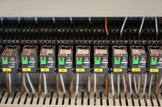
Keep encoder signal cables away from motor power cables and high-current conductors. Use twisted differential pairs where the output supports them, terminate the receiver according to the interface requirements, and verify shield continuity from the encoder or readhead enclosure to the grounding point.
For 8-wire differential A, A-, B, B-, Z, Z- arrangements, use the dedicated rotary encoder line-driver wiring guide to confirm conductor mapping and receiver termination. Omron describes RS-422A line-driver output as a differential method intended for high-speed, long-distance transmission and comparatively resistant to noise [S3].
If a channel is noisy, disconnect the machine drive and compare the encoder output with the motor stopped. Persistent noise points toward grounding, cable routing, shield continuity, or a defective output stage. Noise that appears only during motion points toward radiated interference, common-mode paths, or an inadequately shielded installation.
Verify output timing, direction, and index position
For a 2-phase incremental encoder, verify that phases A and B are normally separated by 90° electrical, and use phase Z as the once-per-revolution origin signal. For clockwise rotation viewed from the shaft end, phase A normally leads phase B; for an absolute encoder, the defined code increase direction establishes the corresponding positive direction [S3].
Rotate the shaft slowly by hand and inspect the waveform at the controller input. Check pulse count per revolution, A-to-B sequence, Z occurrence, pulse width, and signal polarity. Measure maximum operating frequency with the installed cable and receiver rather than relying only on a bench result. The photoelectric sensor comparison is useful for signal timing, but the rotary encoder's phase relationship and index pulse must be verified independently.
Line-driver outputs are preferable where noise immunity and cable distance dominate. Open-collector outputs require suitable pull-up or pull-down arrangements, while voltage outputs use a resistor to convert the transistor output into a voltage signal [S3]. Match the encoder output type to the input module rather than adding an arbitrary relay or voltage interface.
Absolute encoders require a known mechanical reference for commissioning. Establish the reference position, confirm the reported direction, and verify several known angles against the mechanical scale. If the absolute count changes after a power cycle, investigate wiring, communication, data-bit interpretation, and encoder configuration before adjusting the mechanical zero.
Set optical disc and readhead alignment

For a disc-based optical encoder, mount the disc and readhead only after confirming that the disc is clean, undamaged, and correctly seated. ATOM installation follows a defined sequence covering disc mounting, disc alignment, optical alignment, electrical alignment, system connection, and readhead mounting [S1].
Complete optical alignment before electrical alignment. Confirm that the readhead sees a stable signal across the intended disc area and that the disc is not mounted at a tilt that varies signal quality around one revolution. Renishaw's ATOM procedure separates mechanical disc installation and alignment from the later readhead and electrical commissioning steps [S1].
If the encoder produces a weak or intermittent signal, clean the permitted optical surfaces, inspect for scratches, and repeat alignment. Do not repair a cracked disc or damaged readhead with improvised cleaners or coatings. Replace the affected component when contamination cannot be removed without altering the optical surface.
Enclosed systems have different installation constraints. Renishaw publishes separate guides for FORTiS-S and FORTiS-N enclosed encoder systems, including functional-safety variants, multiple-readhead systems, and a separate air-filter assembly mounting document [S5]. Use the model-specific guide rather than adapting the open optical alignment sequence to a sealed unit.
Commission the encoder under real operating conditions
Commission in three stages: uncoupled hand rotation, low-speed machine rotation, and rated operating speed. During hand rotation, confirm smooth motion and stable A, B, and Z outputs. At low speed, verify commanded direction against feedback. At operating speed, compare the displayed angle or speed with a trusted reference and watch for intermittent counts, vibration, or phase errors. [S3]
Record the maximum response frequency permitted for the selected output and compare it with the operating point. Omron defines maximum response frequency as the highest frequency at which the signal can respond, while output rise and fall time describes the transition from 10% to 90% of the output change [S3]. A nominal encoder resolution does not prove that the complete electrical chain can carry the required frequency through the cable and receiver.
Verify shaft load, running temperature, cable retention, connector security, and shield grounding under the actual machine cycle. Omron identifies ambient operating temperature as the external air-temperature range within which specified performance is maintained [S3]. Quantum Devices publishes encoder installation manuals by model for assembly, installation, and handling, making the exact manual a required part of the commissioning record [S2].
Stop and replace or escalate the installation if the shaft binds, the encoder body overheats outside its specified range, the index position cannot be made repeatable, or the output remains unstable at rated speed. These are not tuning conditions to be accepted; they indicate a mechanical, electrical, environmental, or device-selection problem.