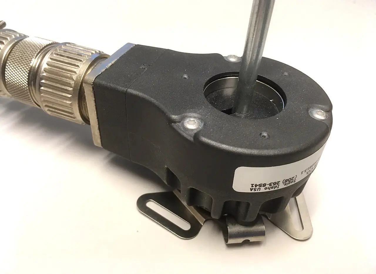
An absolute encoder is a rotary position sensor that reports the actual angle of its shaft as a coded number, not as a stream of counts. Inside, a code disk carries a pattern of tracks read optically or magnetically, and every shaft position maps to a unique word, typically in gray code: 17 bits for 131,072 positions per turn on an ordinary industrial unit, up to 23 bits, more than 8 million positions, on high-resolution optical designs. A multiturn variant additionally remembers the number of complete revolutions, by a geared counter, a battery, or a Wiegand-wire energy harvester, so an axis that traveled 37 turns and 90 degrees while powered down reports exactly that on wake-up. The defining property is retention: position survives power loss, reference runs, and lost counts, which is the failure list of the incremental rotary encoder it replaces.
Specifying one is an interface and resolution exercise more than a mechanics exercise. The buyer picks single-turn or multiturn by whether the machine can home after power-up, picks resolution and accuracy separately because they are not the same number, and then commits the controller side: the classic SSI serial link that any PLC input card reads, or one of the high-speed servo-class links, BiSS, EnDat, HIPERFACE, or an EtherCAT-native encoder profile, that push update rates into the tens of microseconds for closed servo loops. This page works each choice with catalog numbers, draws the line between optical and magnetic sensing by environment, and closes with the RFQ lines that make encoder quotes comparable.
This page treats the absolute encoder as a position authority: gray-code disk mechanics, single-turn versus multiturn retention including Wiegand energy harvesting, resolution versus accuracy versus repeatability, the SSI, BiSS, EnDat, and HIPERFACE interface trade, safety variants, and the RFQ lines that pin all of it down.
Chapter 1 / 06
What an Absolute Encoder Is and What Is Being Decided
The distinction that organizes the whole purchase is absolute versus incremental. An incremental encoder emits pulses; the controller counts them; position is a memory, not a fact. Lose power, miss pulses in noise, exceed the counter's rate, and the machine no longer knows where it is until a reference run. An absolute encoder makes position a property of the hardware: the code pattern on the disk answers what angle is this, whenever asked, with no accumulated history required. That single difference is why absolute feedback owns robotics, multi-axis machines, lifts and cranes, printing and packaging registration, and every axis whose homing run is expensive, dangerous, or simply slow. On a machine that can home in two seconds, incremental remains the economical answer, and honest selection starts by admitting which machine is which.
What is being decided decomposes into five questions. First, single-turn or multiturn: if the working range is under one revolution, a single-turn unit is complete; if the axis travels multiple turns, the turn count must survive power loss too, and the multiturn mechanism, geared, battery, or Wiegand self-powered, is the decision. Second, resolution and accuracy: how finely must position be known, and how truly, which are separate rows on the datasheet and separate costs. Third, interface: SSI for ordinary PLC logic, or a servo-class bidirectional protocol, BiSS C, EnDat 2.2, HIPERFACE DSL, when the encoder talks to a drive at microsecond rates, or an industrial network profile when position rides the fieldbus itself. Fourth, mechanics and environment: shaft sizes, hollow-bore mounting on a servo motor shaft, backlash-free couplings, IP rating, shock and vibration class, temperature. Fifth, safety: whether the axis needs a functional-safety encoder, SIL-rated with redundant scanning, because the safety chain is only as good as its position source.
Neighbors frame the decision. The generic rotary encoder page covers the incremental family in depth; a linear encoder answers the same absolute question for straight-line axes with the same interface logic. At the simple end, an inductive sensor or proximity sensor resolves end-stop and step presence for a fraction of the cost, and a resolver, the absolute encoder's electromagnetic ancestor, still wins on heat and abuse tolerance where its coarse resolution suffices. On the controller side, the encoder is one citizen of the input landscape that also holds IO-Link smart sensors at the device level and a fieldbus gateway or native network port where position must reach the PLC as process data; the interface choice in Chapter 2 is made with that architecture in view.
The purchase is completed by the drive context: on a servo motor axis the encoder is usually motor-mounted and drive-sold as a set, and the buyer's freedom is the interface protocol both ends speak; on a stepper motor axis an absolute encoder is often the upgrade that recovers open-loop lost steps; on a VFD-driven rotating machine, encoder feedback closes the speed loop where process quality demands it. This page assumes the buyer is specifying the encoder as a line item and writes the RFQ accordingly.
Chapter 2 / 06
Coding, Interfaces, and Timing Physics
The code disk is where the physics lives. An optical disk carries concentric printed tracks, one per bit, read by an LED through a mask onto a photodiode array; a magnetic disk carries a magnetized pattern read by Hall or magnetoresistive sensors. Absolute disks are read in gray code, in which adjacent positions differ in exactly one bit, so a sensor edge timing skew can delay a reading by one count but never produce a wildly wrong word, the property binary code lacks and the reason every absolute encoder datasheet in the world says gray at the interface. Resolution is the number of distinct words: 16 bits is 65,536 counts per turn, 17 bits 131,072, 20 bits about one million, 23 bits about 8.4 million, corresponding to angular steps of roughly 20 arcseconds at the top end. Multiturn words add 12 bits for 4,096 revolutions as the standard gear-count, with 14 and 16-bit turn counters and plus-minus bidirectional ranges in the catalog.
Accuracy is a different measurement and must be bought separately. Resolution says how finely the disk can speak; accuracy says how far the reported angle can be from the true angle, and it is dominated by disk eccentricity, code pattern error, bearing play, and shaft coupling error. Typical catalog accuracy runs about plus or minus 60 arcseconds for standard optical single-turns, down to a few arcseconds for premium calibrated units, and one to several arcminutes for magnetic types. Repeatability is usually an order better than accuracy and is the number a pick-and-place or registration application actually trades on. The practical rule: resolution beyond accuracy is interpolation, useful for velocity smoothness, not for position truth, and paying for 23 bits on a mechanism with 2 arcminute backlash is buying a microscope for a moving target.
SSI, synchronous serial interface, is the workhorse: position bits clocked out on request over differential RS-422 pairs, one clock line and one data line, at clock rates up to a few megahertz over short cable runs and derated with length. SSI is unidirectional, the controller asks and the encoder answers, it is gray-coded by convention, monotonic by construction, and it is the interface every serious PLC high-speed input family speaks natively. Its limits are informational: no parameters, no diagnostics, no electronic nameplate, and a latency of one full clock frame per reading, which at 25 bits and 1 MHz is tens of microseconds, fine for logic, marginal for a 62.5 microsecond servo cycle at scale.
The servo-class protocols extend SSI's physical idea with bidirectionality and intelligence. BiSS C is the open standard of that family: bidirectional communication over the same clock and data pairs, position telegrams interleaved with register access, so the drive reads configuration, temperature, and alarms from the encoder on the same wires as the position stream, at clock rates to 10 MHz class. EnDat 2.2 is the Heidenhain proprietary counterpart with the same bidirectional memory model and a large installed base in machine tools, orderable from the drive maker's encoder menu. HIPERFACE and HIPERFACE DSL, Sick protocols, the latter a single-pair digital link riding the motor cable, integrate as the factory feedback of a drive ecosystem. The selection reality: these protocols are chosen with the drive, not before it, because the drive's encoder port list is the compatibility universe; the RFQ's job is to name the protocol, version, and baud-clock class so the two ends arrive speaking the same dialect.
Timing closes the chapter. A servo loop at 8 kHz consumes 125 microseconds per cycle; the encoder must deliver a fresh, timestamped position well inside that, which is what bidirectional protocols with their low propagation delay and, on network axes, what distributed-clock synchronization exist to guarantee. On a 125 microsecond EtherCAT cycle, position telegrams synchronized to sub-microsecond jitter make multi-axis interpolation possible; on a PLC scan measured in milliseconds, SSI latency is invisible. Buy the interface by the loop rate that will consume the data, add cable-length derating margin, and the timing physics stays out of the commissioning log.
Chapter 3 / 06
Types, Mechanics, and Duty Boundaries
Scan technology divides the family first. Optical encoders deliver the resolution and accuracy ceiling: fine code tracks, tight tolerances, and a clean dependency on keeping the optical path clean. Magnetic encoders trade resolution ceiling, arcminute accuracy class at best, for indifference to dirt, oil, dust, moisture, and shock: a sealed magnetic unit runs where an optical disk fogs or fragments, at a lower price, and owns the mid-resolution duties in rough industries. Between them sits every serious catalog's honest segmentation, and the boundary moves with the cleanliness of the machine: a machine-tool axis buys optical, a forestry harvester buys magnetic, a food-washdown axis buys either in the right housing.
Mechanics divides the family second. Shaft encoders, solid or hollow to 15 mm class, couple to the driven shaft through a backlash-free coupling and carry an anti-rotation torque arm or sync flange. Hollow-shaft encoders drop onto the motor or gear shaft directly, eliminating the coupling and its alignment labor, with the torque arm absorbing reaction; through-bore designs let the shaft pass entirely through for customer mechanics. Kit or module encoders are the OEM's component form, an exposed code wheel and scan board integrated into the motor itself at the factory, the way servo motors ship their feedback. The mounting decision is a machine-design decision: hollow-shaft for compactness and no coupling, shaft-plus-coupling for serviceability and thermal isolation of the encoder from the motor.
Multiturn mechanism divides the family third, and the differences are lifecycle economics. Geared multiturns count turns mechanically through a gear train: no battery, no energy harvesting limits, but the gear train adds depth, backlash, and a shock sensitivity. Battery-backed multiturns count electronically and park the count in memory powered by a lithium cell: compact and cheap, with a battery-service clock, typically five to ten years, and an end-of-life telemetry line on better units. Wiegand-wire multiturns harvest energy from the rotation itself: a Wiegand sensor under the shaft magnet generates a pulse each turn, and that pulse both counts and powers the count into nonvolatile memory, removing the battery entirely, which is why Wiegand multiturns dominate axes that must survive years unpowered, valves, actuators, remote machinery, with no maintenance window for a cell swap.
Variant
Resolution class
Environment strength
Hard boundary
Optical single-turn
17 to 23 bit, arc-second accuracy class
Clean, IP65 to 67 sealed
Contamination and condensation kill the optical path
Magnetic single-turn
up to 16 to 18 bit, arc-minute class
Dust, oil, shock tolerant, IP67 to 69K
Accuracy ceiling; strong external fields need care
Geared multiturn
12-bit turn count, 4096 revs
No battery, robust counting
Gear depth, shock sensitivity of the train
Battery multiturn
to 16-bit count, plus-minus range
Compact, low cost
Cell replacement clock, cold-temperature behavior
Wiegand multiturn
to 16-bit count, battery-free
Years unpowered, zero maintenance count
Price step; turn-count rate limits at extreme speed
Functional-safety type
dual scan, SIL3 class
Safe position for safety chains
Cost; needs safety-controller certification match
Duty boundaries in sentences. A 23-bit optical belongs where accuracy is the product, machine tools, metrology, precision registration; a magnetic belongs where the environment is the product, mobile equipment, washdown, outdoor actuators. A multiturn belongs where homing is impossible or expensive; a single-turn with a home switch belongs everywhere else. A Wiegand multiturn belongs wherever the machine may sit unpowered longer than a battery's honesty, and a safety encoder belongs the moment a standard's risk assessment says the position source feeds a safety function. Below all of it, if the question is only is the axis at the stop, the answer is a proximity sensor, not an encoder at all, and above it, if the machine integrates its own feedback, the encoder is a servo-drive line item rather than a catalog purchase.
Chapter 4 / 06
Key Specification Parameters
The decode table is the datasheet skeleton; each row is an RFQ line with a number or a named standard, and each blank row is a compatibility risk.
Parameter
Typical catalog spread
What it decides
Single-turn resolution
16 to 23 bit; 65,536 to 8.4 M counts/rev
Fine position steps and velocity smoothness
Multiturn range
12 to 16 bit; 4,096 to 65,536 revs
Travel envelope retained through power loss
Accuracy
plus/minus 60 arcsec optical to arc-minute magnetic
True position error, distinct from resolution
Interface
SSI, BiSS C, EnDat 2.2, HIPERFACE DSL, network
Controller and drive compatibility, update rate
Update or propagation delay
SSI frame delay to sub-10 microsecond servo links
Loop-rate fit for the consuming control
Mechanics
6 to 15 mm shaft, hollow and through-bore
Mounting method, coupling or torque arm
Environmental class
IP65 to 69K; shock to 250 g, vibration class
Survival in the actual machine envelope
Temperature range
minus 40 to plus 85 or 100 deg C
Cold starts and motor-adjacent heat
Supply and current
5 V or 10 to 30 V; 30 to 150 mA
Input-card or drive supply compatibility
Safety and certificates
SIL3 class dual-scan; CE, UKCA, UL
Use in safety functions and market acceptance
Resolution and accuracy rows must be filled separately, then read together: an axis needs resolution for control smoothness at least an order finer than its mechanical error, and accuracy no better than the process tolerance it serves. When a quote lists resolution but not accuracy, the missing number is the one the application was buying, and requesting it is the whole review.
The interface row carries the compatibility universe. Write the protocol, the version class, and the line rate: SSI gray with the clock rate the cable length allows, BiSS C with register map class, EnDat 2.2 with command set, or the drive-native protocol by name. On network axes, name the profile and the sync class, because position delivered without a synchronized timestamp is position delivered late by a varying amount, which is jitter the servo loop will amplify rather than absorb.
Environmental rows decide warranty claims. Shock and vibration to IEC 60068 classes, IP rating matched to washdown or dust reality, condensation behavior for outdoor and cold-room axes, and the temperature band including the motor-adjacent installation point, are the rows that separate identical-looking quotes in the field. Bearings on shaft encoders are consumables rated in speed-hours at temperature; hollow-shaft designs with torque arms trade that clock away. And the supply row matters more than it looks: a 5-volt-only unit on a 24-volt machine is an extra converter, and current draw times axis count is an input-card budget line.
The safety row is binary in effect: a standard encoder may not feed a safety function, a safety encoder carries dual scanning and a certificate chain, and the drive or safety controller it pairs with must accept its protocol's safety telegram. Buy the safety encoder with the drive, or the certification seam between them becomes the project's next meeting.
Chapter 5 / 06
Selection Decision Factors and RFQ Language
The sequence runs application truth to interface to mechanics, and the questions are short when asked in order.
State the motion task: working travel in revolutions, required position knowledge after power loss, and whether a homing run is possible at all. This decides single-turn versus multiturn and the turn-count mechanism.
State the process tolerance in shaft-angle terms and the mechanical error budget of the machine. This separates the accuracy requirement from the resolution requirement and prices each correctly.
State the consuming control: PLC scan or servo cycle rate, and the drive or controller's supported encoder list. This fixes the interface and its line-rate class.
State the environment: shock, vibration, washdown chemistry, condensation, temperature extremes, and cable-run length with routing. This fixes scan technology, IP class, and line-rate derating.
State the mounting reality: shaft access, coupling or hollow-shaft space, torque-arm geometry, and service clearance. This fixes the mechanical form.
State the safety question: does position feed a safety function, and under which standard's performance level. This adds or removes the safety-encoder row.
Write the RFQ with every Chapter 4 row, protocol version class included, and evaluate quotes row against row.
Cost behavior is tiered by interface and turn logic. As a planning spread: a magnetic single-turn with SSI sits at the family baseline; an optical single-turn of equal bits runs 1.5 to 3 times; multiturn adds 30 to 100 percent by mechanism, Wiegand at the top of that band; servo-class interfaces add 20 to 60 percent over SSI at equal optics; and safety versions multiply their base by 2 to 3. Against neighbors, a quality absolute unit prices several times an incremental rotary encoder package and a large multiple of the proximity switch that answers only is it there; against a linear encoder of equal accuracy on a straight axis, prices converge by travel. The comparison table holds the real trades.
Option pair
Relative cost
What you gain
What you pay in
Incremental vs absolute, same optics
1.0 vs 1.5 to 2.5
Position retention, no homing
Price; sometimes interface complexity
SSI vs BiSS C or EnDat
1.0 vs 1.2 to 1.6
Parameters, diagnostics, servo rates
Drive-side support requirement
Magnetic vs optical single-turn
1.0 vs 1.5 to 3
Resolution and accuracy ceiling
Contamination sensitivity
Battery vs Wiegand multiturn
1.0 vs 1.2 to 1.5
Battery-free life, zero maintenance count
Price step on long-unpowered axes
Standard vs SIL-class safety unit
1.0 vs 2 to 3
Legal position source for safety functions
Cost, drive certification match
The RFQ checklist, written to copy: single-turn bits and total counts; multiturn bits, revolution range, and mechanism; accuracy in arcseconds or arcminutes with the measurement basis; repeatability; interface with protocol, version, and line rate; update behavior and delay; electrical supply and current; mechanical form with shaft or bore dimensions and coupling or torque-arm provision; IP, shock, vibration, and condensation class; temperature band; safety class with certificate reference; cable or connector standard, M12 by default, with length and shielding; and the accessory list, coupling, torque arm, cables, connectors, ordered with the unit so one vendor owns the fit.
System integration closes the selection. The encoder joins a machine whose controller landscape includes the PLC that supervises it, the IO-Link infrastructure of its simpler sensor neighbors, and, on coordinated axes, the drive network with its synchronized clocks; a fieldbus gateway bridges legacy islands, but position data for servo loops should ride native links, not conversions. And the soft starter on the next panel has no interface in this conversation, it shares only the cabinet: the discipline is matching the encoder interface to the loop that consumes its data, which is the difference between position as process knowledge and position as another alarm to acknowledge.
Chapter 6 / 06
Installation, Standards, Failure Modes, and Maintenance
Installation discipline is alignment and cable hygiene. Shaft encoders demand a backlash-free coupling aligned within the coupling maker's angular and parallel limits, typically a few hundredths of a millimeter at the coupling rim; misalignment shows up later as bearing failure and count jitter. Hollow-shaft units demand correct torque-arm anchoring with the prescribed slack, because a rigid arm converts motor vibration into encoder case stress. Cable runs respect bend radius in energy chains, separation from power conductors, and continuous shield termination at both ends through 360-degree clamps, because the differential lines survive only as a transmission-line pair. Connectors seat and lock; M12 threads carry their torque spec, and the first commissioning step after wiring is a static position check at a known angle, recorded, so every later doubt has a baseline to meet.
Commissioning verifies the interface contract, not just a live number: correct gray-to-binary conversion at the controller, correct total-count scaling per revolution, monotonicity through one slow revolution, turn counting verified through several revolutions and a power-cycle, because the retention property is the entire purchase. On bidirectional protocols, read the encoder's electronic nameplate and alarm list and confirm the drive's parameter set matches; on safety units, complete the acceptance test the safety manual prescribes and file it with the machine's validation records.
The standards frame is a stack of interface specifications and environmental classes rather than one product standard: SSI as a de facto industry convention documented by encoder makers; BiSS as the open interface specification of the BiSS Association; EnDat 2.2 and HIPERFACE as their owners' published specifications, integrated into drive ecosystems and covered in the drive-profile standards family IEC 61800-7; environmental and EMC testing by the IEC 60068 and IEC 61000 series; and functional safety by IEC 61508 with the machinery implementation in IEC 62061 and ISO 13849. A datasheet that cites these by number is a datasheet that was written to be checked, which is the posture an RFQ should reward.
Failure modes rank with field history. Contamination of the optical path, dust, oil mist, condensation, leads for optical units: symptoms are wild multi-bit words or intermittent alarms, and prevention is the IP class and a desiccating breather where condensation is real. Bearing wear follows on shaft units, heard before it is seen as position noise at constant speed; the cure is alignment discipline and the scheduled replacement the speed-hours predict. EMC corruption appears as lost or corrupted frames on long unshielded runs: the cure is cable hygiene and line-rate derating, not retries. Coupling failure and torque-arm fatigue present as intermittent count loss and are found by inspection at the intervals vibration exposure sets. Battery end-of-life is a scheduled event on battery multiturns, announced by telemetry on better units; ignoring it converts a multiturn into a single-turn with an opinion. And mechanical overload, a dropped unit, an over-torqued coupling, kills accuracy without killing output, which is why the acceptance recheck after any mechanical incident is a known-angle comparison against the commissioning baseline.
Maintenance for a sealed encoder is therefore mostly absence: no lubrication, no adjustment, no calibration in place; what remains is verification. Re-verify the known-angle baseline after mechanical work on the axis, re-verify turn counting after any battery event or long storage, keep couplings and torque arms in the inspection round, and retire units by bearing hours and incident history rather than by failure. The encoder's reliability model is why it was bought: position as a hardware fact, and the maintenance plan's whole job is not to argue with that fact but to keep checking it cheaply.
FAQ
What does an absolute encoder keep after power loss that an incremental one does not?
The angle, and in multiturn versions the revolution count. The code disk pattern reports the shaft's actual position on request with no counting history; a Wiegand or geared multiturn keeps total turns unpowered for years. An incremental encoder reports only motion pulses, so its controller's count is memory, and power loss forces a homing run.
How many bits of single-turn resolution do I actually need?
Match the machine, not the catalog ceiling. 16 to 17 bits, 65,536 to 131,072 counts per revolution, covers most PLC-class axes; 20 to 23 bits serve precision registration and metrology where mechanics deserve it. Resolution finer than the axis's accuracy is interpolation for velocity smoothness, not more true position.
SSI, BiSS, EnDat, or HIPERFACE, which do I order?
Choose with the drive or controller, not in the abstract. SSI is the universal PLC input; BiSS C is the open bidirectional standard; EnDat 2.2 and HIPERFACE belong to their drive ecosystems. The RFQ must name the protocol and version class so both ends of the wire speak the same dialect.
Why is a multiturn encoder without a battery better for valve actuators?
Wiegand-wire multiturns harvest counting energy from rotation itself, so the turn count survives years unpowered with no cell to replace. Valves sit idle for long periods and must report true stem position on demand; a battery clock is a maintenance liability exactly there.
What is the difference between resolution and accuracy here?
Resolution is the number of distinguishable positions, 17 bits being 131,072 counts per turn; accuracy is how far the reported angle may sit from the true angle, roughly plus or minus 60 arcseconds class for optical and arc-minute class for magnetic. Buy resolution for control smoothness, accuracy for position truth, and check both rows on the datasheet.
Can a standard encoder feed a safety function?
No. Safety functions need a safety encoder with redundant scanning and a certificate chain to IEC 61508 or ISO 13849 performance levels, paired with a drive or safety controller that accepts its safety telegram. The safety purchase is made with the drive, not bolted on after.
Why did my optical encoder start reporting wild positions in winter?
Condensation in the optical path is the classic cause: sealed does not mean dry, and temperature cycling breathes moisture through every cable gland. The fixes are the correct IP and condensation class for the location, a desiccating breather, and cable-entry discipline; the diagnostic is wild multi-bit words that clear as the unit warms.