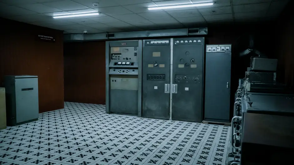
Disconnect the AC cord and every DC connector before removing a switching power supply, then install the replacement with keyed connectors, correct airflow, and an independent power-on check [S1][S4].
This procedure applies to modular computer PSUs and rack-mounted network-switch power supply modules; product-specific guides control where the procedures differ, especially for live switch operation, DC input, and hot-swap behavior [S2][S3].
Isolate the power supply before touching connectors
For a desktop-style PSU, disconnect the AC cord from both the wall outlet and the PSU, then unplug all DC cable connectors [S1]. Remove the four mounting screws before extracting the old unit [S1]. This sequence removes two independent energy paths and prevents a cable from carrying load into a partly disconnected module.
Do not open the PSU cover, insert objects into the fan grille, or obstruct the ventilation area [S1]. High voltage can remain inside, and the cited installation guide states that opening the cover voids the product warranty [S1]. Keep the unit dry and use the specified AC cord and modular cables [S1].
For rack switches, the removal procedure also calls for disconnecting the AC cord from the wall outlet and the PSU input before releasing the module [S3]. This is the correct first action for an AC-installed module even when the switch chassis remains powered through another supply or feed.
Verify the replacement against the equipment requirements
Confirm the model name on the rating label, input requirements, output ratings, connector set, and approved cable set before installation [S1]. A PSU may have the same physical envelope as another model while differing in input voltage, output current, rail sequence, modular connector pinout, and fan-control behavior [S5].
Compare the replacement against the unit being removed rather than against appearance alone. For modular PC cables, ASUS identifies connector insertion technique as a means of avoiding damaged connectors, abnormal power-supply behavior, or incorrect connections [S6]. The Seasonic procedure separately identifies 18-pin, 10-pin, and 24-pin motherboard connections, so connector count alone is not a complete identification method [S1].
Use the equipment manufacturer’s installation manual as the controlling document.
Compare installation types and connector interfaces
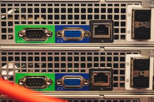
The comparison below separates the practical constraints that determine whether a replacement can be installed safely and operated correctly.
Set airflow and mechanical position before connection
Do not place any object in front of the power supply unit's fan or ventilation area that may obstruct or restrict airflow [S1]. The governing acceptance test is unobstructed airflow, not the orientation label alone.
Keep cables and objects clear of the fan and ventilation area [S1]. This is a pre-install functional check and does not replace load, polarity, or protection testing.
For rack equipment, secure the module according to the chassis latch or fastener arrangement. Cisco documents power supply module replacement for the C9350 series, while Extreme Networks requires the AC cord to be disconnected at both the outlet and power input before the latching tab is pressed and the unit pulled outward [S2][S3].
Connect the DC leads without forcing the keying
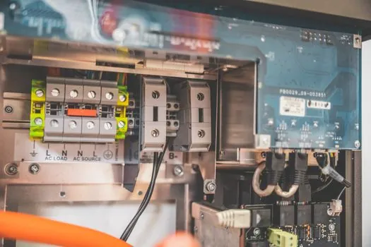
Before removing the old PSU, disconnect its AC power cord from both the wall socket and the back of the power supply and disconnect all DC cable connectors [S1]. Align each connector with its socket before applying force.
A tester or the documented paper-clip method checks that the PSU can start, but it does not prove that every DC rail has the correct voltage, regulation, or load capacity. For an industrial or network installation, verify the model rating and output test points against the equipment specification before energizing the load.
Do not substitute a modular lead based only on pin count. The cited modular-cable guidance requires correct insertion to prevent connector damage, abnormal PSU operation, and incorrect connection [S6]. Keep unreferenced DC outputs disconnected unless the equipment instructions require otherwise.
Perform a controlled startup before attaching the load
For a rack switch, verify the module seating, latch engagement, and front-panel power-supply indicators after insertion [S2][S3]. If the C9350 installation is permitted while operational, follow its module and redundancy procedure rather than assuming an uncontrolled shutdown is acceptable [S2].
Reject the installation if a connector requires force, the module will not seat in one keyed orientation, airflow is blocked, the fan remains stationary in Normal mode, or the expected power indicator fails [S1][S4]. Do not repair a failed PSU by opening it; isolate it and replace or escalate it for qualified service [S1].
Troubleshoot common installation failures
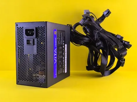
<strong>Symptom: the fan starts but the system does not.</strong> Root cause candidates include a reversed, incompletely seated, or incorrectly pinned DC connector. Disconnect power, inspect the keying and seating, and replace or reseat the lead without forcing it [S4][S6].
<strong>Symptom: there is no fan movement or test indication.</strong> In Normal mode, confirm that the I/O switch is ON and that the AC cord is connected at both the outlet and PSU [S1]. If the PSU is set to Hybrid or Fanless mode, use the model-specific fanless test procedure instead [S1].
<strong>Symptom: the system faults immediately after module insertion.</strong> Remove the module, compare its model and ratings with the original, verify connector orientation, and check that the module is fully seated [S2][S4]. Escalate to the switch vendor when the supported hot-swap or redundancy sequence is unclear.
<strong>Symptom: the unit overheats after installation.</strong> Restore the specified airflow orientation and remove obstructions from the fan or ventilation cover [S1]. Replace the unit if it still overheats or shuts down, rather than enclosing a suspect PSU or overriding thermal protection [S1][S5].
Complete the installation record
Record the PSU model, input voltage and frequency, output ratings, cable identifiers, installation orientation, and startup result in the equipment maintenance record [S5]. The Mean Well technical manual organizes verification topics around input voltage and frequency, output voltage tolerance and adjustment, maximum output current and power, protection functions, and Power Good or Power Fail signaling [S5].
Close the task only after the mechanical, electrical, thermal, and operational checks match the manufacturer’s model-specific criteria. Replace or escalate the module if it cannot be fully seated, lacks correct airflow, fails the startup indication, or has undocumented output behavior [S1][S2][S4]. A complete installation record should also identify the connected DC loads and the observed module or system status, not merely state that the PSU was fitted [S2][S3].