
A correct DC-DC converter installation starts with matching the 6–60 VDC input to the rated load, then checking polarity, fuse ratings, ventilation, and output regulation before energizing the circuit.
The procedure applies to non-isolated and isolated converters, including 5 V buck units, vehicle power systems, and industrial DC power supplies; the exact connector, cable, and fuse requirements remain model-specific [S1][S2][S3][S5].
Verify the converter ratings before wiring
The installation envelope must be established before any conductor is connected. For example, Honeywell model 851-070-003 accepts 6–60 VDC and provides 14 A, while model 851-041-003 uses a 2-pin connector with a 15–96 V input range [S1]. These figures describe model-specific hardware and must not be transferred to another converter without its manual.
For a step-down supply rated from 8–32 VDC to 5 V at 5 A, the nominal output power is 25 W. That power is confirmed by the 5 V output and 5 A current rating in the MZHOU manual [S4]. At the other end of the range, an 8–40 V input to 5 V converter must remain inside both its stated input window and its output current limit throughout battery charging, load steps, and ambient conditions [S3].
Record the converter’s exact model number, input voltage range, output voltage, rated current, polarity, isolation rating, fuse type, and permitted operating temperature. If one of those values is absent from the datasheet or installation guide, do not infer it from a similar device. The CV60 guide, for example, provides separate sections for the power supply kit, input cable, inline fuse, output cable, cable termination, and mounting [S2].
Choose the topology against the actual load
Topology selection determines isolation, efficiency, footprint, and electromagnetic-interference behavior. A buck converter is appropriate when the input remains above the regulated output across normal operating conditions, while an isolated topology provides galvanic separation when the source and load grounds must not be shared [S3].
The source describes DC-DC converter types and characteristics for 8–40 V to 5 V designs, including flyback and half-bridge converters [S3]. Integrated modules are compact and straightforward to implement, but their thermal limits can be decisive inside an enclosure. The source describes flyback converters as isolated designs that store energy in a transformer core and as having lower efficiency than non-isolated types [S3].
Prepare the site, wiring, and protection
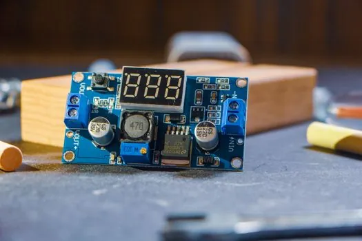
Installation preparation requires mechanical restraint, correct conductor sizing, accessible protection, and a defined grounding arrangement. The converter should be mounted so that its cooling path is not obstructed, cable strain is not transferred to terminals, and service access remains possible.
Verify input polarity at the converter terminals and at the source. A reversed battery connection can stress the input bridge or switching devices, so polarity must be confirmed against the marked positive and negative terminals rather than inferred from cable color. Dometic DCDC06, DCDC12, and DCDC24 units are switched-mode, uninsulated voltage converters with internal input and output protection, and their front LED provides an operating-state indication [S5].
Do not assume that an internal fuse makes the upstream wiring expendable. The inline fuse in the CV60 installation remains a separate installation component, and its rating and location must match the guide [S2]. For a DC-DC converter, use only the fuse type, holder, interruption rating, and wire gauge specified for that model. Replace a blown fuse with the identical prescribed rating; repeated operation with a blown fuse is a fault condition requiring investigation, not a reset procedure.
Terminate cables and verify polarity
Cable termination is a process with measurable acceptance criteria, not a generic instruction to “connect correctly.” A sound installation has no exposed conductor beyond the terminal or crimp barrel, no loose strands, and no mechanical pull load on the connection.
Clean and tighten the termination, then perform a continuity check to confirm that the positive path is connected to the marked positive terminal and the negative path to the marked negative terminal.
Where the converter is not isolated, determine whether the source and load grounds are intentionally common. Grounding by convention is unsafe: a damaged cable or supply fault can place the full input voltage on a supposedly signal-ground conductor. If an industrial router, controller, or other grounded device connects to the converter output, verify the intended common-reference arrangement before energization.
Energize unloaded and validate the output
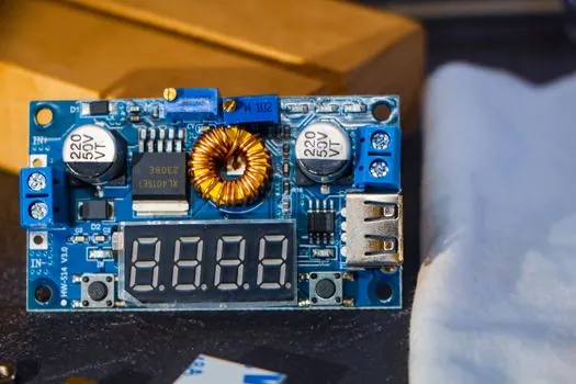
First energization should be unloaded unless the manufacturer’s procedure explicitly defines a different sequence.
After switching on, verify that the output voltage is within the specified limit at no load. The DCDC06, DCDC12, and DCDC24 installation manual identifies the front LED as the operating indicator, so a lit LED confirms an energized state but does not prove that the output voltage or regulation is correct [S5]. Measure the output at the load terminals, not only at the converter, because cable resistance and long cable runs can create measurable voltage drop.
Reconnect the load in stages and compare output voltage with the model’s specified tolerance and ripple limits. For the 5 V, 5 A converter, verify that the load remains at or below 5 A and that the output does not collapse during connection of the highest expected load [S4]. If the output falls, shuts down, or becomes unstable, disconnect the load and inspect input voltage, polarity, fuse continuity, terminal tightness, and converter temperature.
Troubleshoot by symptom, cause, and corrective action
No output with an illuminated indicator is not proof of a failed converter. The CV60 troubleshooting sequence checks the power supply, cables and connections, and fuse as separate items [S2]. Corroded terminals, an open cable, an incorrect source connection, or a blown fuse can mimic converter failure.
Intermittent shutdown under load points to input sag, an inadequate source, excessive current draw, or thermal stress. Correct the cause by restoring the source voltage, removing excess load, checking conductor and fuse sizing, or improving cooling. Do not raise the fuse rating or increase the output current beyond the converter rating. A converter that remains hot, smells abnormal, or exhibits damaged insulation should be de-energized, isolated, and replaced or escalated for service.
Unstable 5 V output can result from incompatible source voltage, excessive input ripple, a faulty connection, or an overloaded output. Compare measured input and output waveforms with the manufacturer’s limits, inspect the load, and verify the input range before replacing the unit. The CV60 guide also treats inline-fuse replacement as part of maintenance, but replacement should follow the specified fuse type and rating [S2].
Document commissioning for maintenance and upgrades
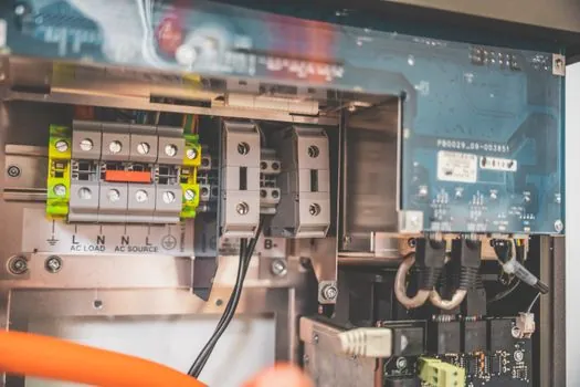
Commissioning is complete only when the installation record contains reproducible measurements. Capture the converter model, source voltage before connection, no-load output voltage, loaded output voltage, load current, ambient temperature, input polarity, fuse rating, mounting location, and the dates and identifiers of the personnel performing the checks [S2].
Record any deviations from the manufacturer’s procedure, including added adapters, splices, cable extensions, or changed load equipment. For a 5 V output, establish the measured voltage under both nominal and maximum expected load so later failures can be distinguished from an installation defect. Retain the procedure linked to the industrial UPS if the converter is part of a backup-power arrangement, because battery charging and transfer behavior can alter the converter’s real input profile.
The final acceptance check is straightforward: rated input range confirmed, polarity verified, prescribed fuse installed, connections secured, cooling unobstructed, no-load and loaded outputs within model limits, and protection behavior documented. If any result is missing or outside specification, leave the affected circuit out of service until the discrepancy is corrected.