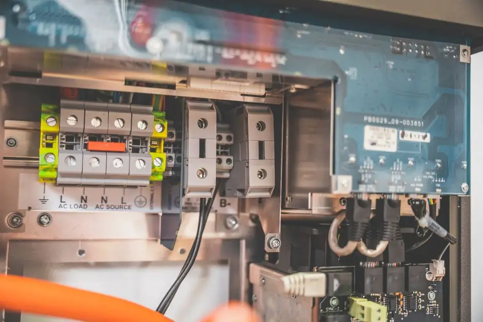
An 8-wire incremental encoder with differential line-driver output exposes six signal conductors (A, A-, B, B-, Z, Z-) plus power and ground, with phase A and phase B separated by a 90 degree electrical angle and phase Z firing once per revolution as the index pulse [S3].
The pin map is consistent across manufacturers: Red = VCC, Black = 0 V, Green = A, White = B, Yellow = Z, Brown = A-, Grey = B-, Orange = Z-, in a 6 mm shaft, 38 mm body, 2000 PPR optical encoder with a 5 VDC line driver [S2]. A complete hookup also requires understanding the rotary encoder output circuit types before choosing between open-collector, voltage, complementary, and RS-422 line-driver variants.
Channel identification on the cable
Channel identification is the first step before any conductor is landed. In the 6-channel cable of a line-driver encoder, the green/white/yellow triplet carries the non-inverting outputs (A, B, Z) while the brown/grey/orange triplet carries the inverting outputs (A-, B-, Z-) [S2]. Power and return are red (VCC) and black (0 V), and the cable shield should be bonded to the encoder housing and to the receiver-side ground at one end to control common-mode noise.
Pin tables on industrial encoders follow the same logic with pin numbers: pin 15 is phase A negative, pin 17 is phase B positive, pin 17 mirror is phase B negative, pin 19 is phase Z positive, and pin 19 mirror is phase Z negative [S3]. For anyone new to the format, the rotary encoder wiring diagram fundamentals article on the encyclopedia breaks down a one-page schematic showing the encoder block, the +5 V/0 V feed, and the six twisted pairs routed to the line receiver.
Why line driver needs both true and complement wires
Line-driver output is defined as an RS-422 differential pair: the IC drives a non-inverting line and a complementary inverting line simultaneously, so the receiver evaluates the voltage difference, not the absolute level, which makes the signal tolerant of common-mode noise on long cable runs [S3]. This is why a 5 VDC open-collector encoder only needs A, B, and Z plus power, while a line-driver part needs the A-, B-, Z- complement trio as well.
Termination matters: a 120 ohm resistor is placed across each differential pair (across A to A-, B to B-, Z to Z-) at the receiver end of the cable, matched to the characteristic impedance of twisted-pair cable, to suppress reflection ringing on edges faster than the rise and fall time of the line driver. An open-collector output cannot be probed on a scope without a pull-up resistor because the transistor collector is genuinely open, while a line-driver output is actively driven and will show a clean square wave at the receiver [S2].
Connecting to a microcontroller or PLC counter

Connecting to a microcontroller, a typical approach is to feed A+, B+, and Z+ into three interrupt-capable GPIO pins on an Arduino or Teensy, and tie A-, B-, and Z- to ground only if the line receiver is single-ended, which defeats the noise immunity of RS-422. The correct approach for a true differential receiver is to use a 26LS32 or AM26LS32 quad line receiver that converts the differential pair back to TTL/CMOS levels, then route those single-ended outputs into the MCU counter pins. [S2]
On a PLC high-speed counter card, the encoder inputs are already differential and the A-/B-/Z- terminals are screw terminals, not ground. The card applies its own 120 ohm termination and a 5 VDC sense supply on the encoder power pin, which is why industrial wiring diagrams list the same six signal conductors without a separate ground wire for the complements. Industrial guidance in the EPC installation manual explicitly states that line-driver encoders ship A and A-, B and B-, Z and Z- as complementary pairs and that the installer must verify and match pin numbers before applying power [S4].
Quadrature, index, and what Z actually does
Quadrature decoding, the index channel Z (and Z-) fires once per mechanical revolution as a one-pulse-per-turn reference, used to mark a known home position and to correct cumulative count drift in incremental systems [S3]. The A and B channels are 90 degrees out of phase electrically, so direction is recovered by checking which edge of A leads B when the shaft is viewed from the end: clockwise rotation, as defined for incremental encoders, means phase A leads phase B [S3].
Index alignment, on a motor-mounted encoder such as the PITTMAN Z Series, the index pulse is factory aligned to the U/V/W commutation channels within plus or minus 45 electrical degrees, which permits drop-in replacement without re-initializing the drive on every motor swap [S5]. This is also why datasheet figures list INDEX ALIGNMENT REF. alongside the A/B/Z output waveforms and the commutation timing diagram.
When the line driver is overkill
Line driver overkill, single-ended push-pull or NPN open-collector output is sufficient when the cable is short (under roughly 2 m), the encoder sits in a benign electrically quiet cabinet, and the maximum response frequency is well below the cable's bandwidth limit. The 5 VDC open-collector variant, in particular, only needs three signal wires plus VCC and 0 V, and works directly into any MCU GPIO with an external pull-up. [S3]
Line driver is not optional when the cable run exceeds several meters, when the encoder is mounted on a VFD-driven motor with switching noise, or when the application's maximum response frequency approaches the line driver's 500 kHz ceiling, as on the PITTMAN Z Series where all six channels are specified at 500 kHz [S5]. For long runs, the differential pair's common-mode rejection is what keeps the count from losing pulses to coupled noise. The rotary encoder selection and resolution guide covers where 5 VDC line drivers are common in servo feedback loops versus where 12-24 V push-pull is preferred in plant-floor discrete applications.
Verification checklist before power-on
Verification checklist, before applying power, confirm: (1) the encoder supply voltage matches the data sheet, with 5 VDC plus or minus 5 percent being the most common line-driver rating; (2) the cable is a twisted pair for each channel plus its complement, not a parallel ribbon; (3) the 120 ohm termination resistor is in place across each pair at the receiver, not at the encoder; (4) the shield is bonded at one end only to avoid a ground loop; and (5) the maximum response frequency in Hz, calculated as PPR times RPM divided by 60, is below the 500 kHz line-driver ceiling for the typical 1000-2000 PPR Z Series encoder [S5].
After power-on, scope each differential pair at the receiver end with the ground clip on the receiver 0 V, not on the encoder end, and confirm a 90 degree phase offset between A and B and a single Z pulse per revolution. If the Z pulse is missing, the most common cause on a 6-wire plus power cable is that Z- has been left open while the receiver expects it terminated, or that the Z pair has been swapped with an unused motor commutation wire on a Z Series motor pigtail [S5].
Trackable signal: check encoder manufacturer datasheets for the next revision of the EPC installation and wiring guide on encoder.com, which has historically published revised pin tables within 12-18 months of each major Opto-ASIC or housing change. Another near-term watch item is the RS-422 receiver IC supply chain, since 26LS32/AM26LS32 shortages have driven some panel builders to substitute isolated RS-485 transceivers, which work but invert the idle-line state on the Z index channel. For related motion-control reading, see Do cobots need a safety fence after risk assessment? on the safety-side constraints that often dictate whether the encoder sits inside a fenced cell or on an exposed cobot joint.
Detailed specification references: pile driver, and wiring duct.