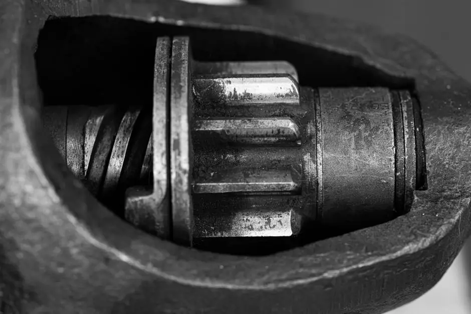
A round pin key is a circular cross-section fastener that seats half in a drilled hole in the shaft and half in a matching hole in the hub bore, with a standard dowel-pin diameter typically chosen between one-third and one-half of the shaft diameter [S2][S3].
Unlike a shaft key that slides into a milled keyway along the shaft axis, the round pin key locks the joint radially: a single transverse hole passes through both members, and the pin is pressed in to lock torque transmission [S2][S5].
Geometry of the Drilled Round-Pin Joint
The round key is a cylindrical pin, and its keyway is a drilled hole, so the joint is the simplest of the five main key families defined in mechanical-engineering references: sunk, saddle, tangent, round, and spline [S2]. In the classic configuration the hole is drilled through the hub and into the solid shaft, with roughly half the pin diameter engaging each member [S3][S5]. When the hole and pin are tapered, the joint becomes a taper pin, sometimes called a Dutch pin, drawing the hub onto the shaft as the pin is driven in [S2].
Because the round key has no longitudinal keyseat, it is a purely radial anti-rotation device, not an axial locator. The hub is free to slide along the shaft until an external stop, snap ring, or shoulder is added. Drilling the hole after the hub is mounted on the shaft is the field-fabrication trick repeatedly recommended in shop practice: the assembled bore and shaft are drilled and reamed as a single stack, guaranteeing the two half-holes stay coaxial without needing a tight press fit first [S5][S6].
Why the Shaft-Hub Fit Controls Everything
Round-pin keys transmit torque only by shear in the pin and by bearing against the half-hole in each member, so any clearance between the hub bore and the shaft OD lets the joint "roll" or "walk" and the pin sees a prying load rather than pure shear [S1]. Practical-machinist engineers have documented the failure mode for decades: a round key relies on a very good fit between the bore in the hub and the shaft to avoid a rolling up or wedging action, which means the joint is essentially a transition between an interference fit and a keyed fit [S1].
This is why round-pin keys are normally limited to lower-torque, non-reversing service. The 2005 Practical Machinist thread that framed the modern discussion proposed a half-inch (12.7 mm) dowel pin for a 1.5 in (38.1 mm) shaft driving a bandsaw bandwheel, predicting a future 18 to 20 hp load at 750 rpm, unidirectional, no shock [S1]. At that shaft size the pin is roughly 33% of the shaft diameter, which sits inside the one-third to one-half dowel-pin rule of thumb cited in distributor literature [S3].
Comparison With Parallel, Woodruff, and Taper-Pin Joints
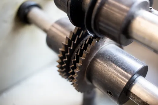
Round-pin keys, parallel sunk keys, and Woodruff keys differ on four criteria that drive selection. On axial locate capability, parallel and Woodruff keys provide positive axial location when the keyway is closed at the shaft end, while the round pin key only resists rotation [S2][S4]. On torque capacity per unit length, parallel and Woodruff keys engage along the full keyseat length (typically 1.5 to 2 times the shaft diameter for a parallel key), whereas a round pin key is a point load at one radial plane, so its capacity scales with pin diameter, not length [S2][S4]. On misalignment tolerance, the round pin key is the worst because any bore-to-shaft clearance shows up as a prying load on the pin, while a Woodruff key's deep circular seat accommodates small angular errors [S1][S2]. On field fabrication, however, the round pin key is the easiest, requiring only a drill and reamer through the assembled stack, with no keyseater, broach, or Woodruff cutter needed [S3][S5][S6].
Sizing, Materials, and Installation Practice
Pin diameter selection follows two practical rules. The conservative rule is to size the pin at one-third of the shaft diameter for general service, the aggressive rule is up to one-half of the shaft diameter when torque demand is high and the shaft is short and stiff [S3]. Hardened ground dowel pins (typically Rc 60+, hardened to ISO 8734 or ANSI B18.8.2) are the standard stock item because they are finish-ground to tight diameter tolerance, which is the second critical parameter after the hole size [S3][S5].
Installation is a press fit: the hole is drilled and reamed to a diameter a few tenths of a millimetre under the nominal pin diameter, and the pin is pressed in with an arbor press. A common field shortcut is to drill slightly undersize and then drive the pin in to create an effective light press fit [S6]. Where frequent disassembly is required, a lightly oiled or even greased pin is acceptable only if torque is low, because lubrication drops the friction coefficient and lets the pin slip in the hole under load [S1][S5]. The shop-fabrication technique is consistent across sources: mount the pulley or coupling on the shaft, then drill and ream for the pin through both members in one setup, which guarantees alignment without requiring a precision slip fit between bore and shaft first [S6].
Failure Modes and When Not to Specify a Round Pin Key

Three failure modes dominate. Shear of the pin is the design mode and the desired one, because the pin is meant to be the sacrificial element that protects the shaft and hub from more expensive damage [S4]. Bending fatigue of the pin is the misapplication mode, occurring when bore-to-shaft clearance is too loose and the pin is loaded in 3-point bending every revolution [S1]. Hub bore elongation or "wallowing" is the wear mode, occurring at the half-hole in the softer member (usually the hub) when the joint runs for many cycles under fluctuating torque.
Round-pin keys are inappropriate for reversing drives, for shock-loaded applications such as punch presses and rock crushers, and for any application where the shaft and hub cannot be made to a tight slip fit (typically ISO H7/g6 or better). They are appropriate for bandsaw drives, small conveyor pulleys, low-speed agricultural shafts, and similar 1 to 20 hp unidirectional drives where field drill-press assembly matters more than a high torque-to-weight ratio [S1][S3]. For high-cycle, high-torque service the engineering reference is to a shaft collar with a hardened setscrew or to a parallel sunk key of the type catalogued in any machine-key handbook [S2][S4].
Standards, Sourcing, and Related Mechanical Joints
Standard stock for round-pin keys arrives as precision dowel pins made of alloy steel, case-hardened to Rc 60 to 62, ground to a diameter tolerance of -0 to +0.005 mm on small sizes, in nominal metric and inch increments [S3][S5]. Distributors such as Reid Supply and Huyett stock these pins in 1/16 in (1.59 mm) to 1 in (25.4 mm) diameters as standard catalog items, with longer and larger pins made to order [S3][S4].
For adjacent mechanical joints, the round-pin key sits in a family with other anti-rotation devices. The gib-head key and feather key are variants of the parallel sunk key family; gib-head keys add a protruding head for easier removal, and feather keys permit axial sliding of the hub on the shaft, both more elaborate than a single drilled pin [S3][S4]. Where the application demands both torque transmission and a controlled axial preload, a shaft collar clamped to the shaft provides the axial lock that a round pin key cannot.
Trackable signals for the next design review: a new ISO revision to dowel-pin tolerances under ISO 8734 is the most likely standard update to watch, while shop-floor adoption of through-drilled round-pin joints continues to grow in low-horsepower farm and conveyor equipment where field repairability outweighs torque density. For machinery builders evaluating higher-torque alternatives at the same shaft size, the comparison with roller vs ball bearing selection logic is a useful parallel: both decisions trade a tighter, more precise interface (interference fit or line-contact rolling element) against a simpler, cheaper, more easily assembled one (a slip fit with a pin or a deep-groove ball bearing).
For component-level specifications, see hmi panel.