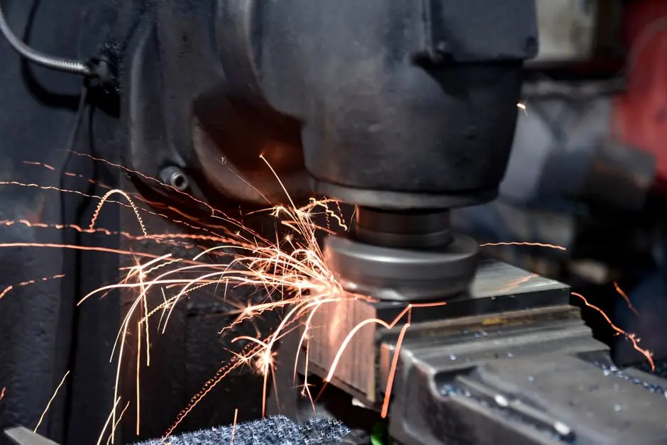
Type 4 electrosensitive protective equipment with 30 mm resolution and IP67 housings is the dominant specification on new robotic welding cells, with sensing ranges typically quoted at 15 m and OSSD semiconductor outputs [S5].
Welding cells expose protective devices to weld spatter, UV/IR flash, and induced heat, so the selection is governed less by reach distance and more by optical stack-up, enclosure, and the standard IEC/EN 61496-1 type classification [S5][S3].
Why a Type 4 / SIL 3 Device, Not Type 2
Type 4 (ESPE category 4) devices such as the Pepperl+Fuchs SLC30-1500-S are self-monitoring and qualified for hand protection at 30 mm resolution, versus Type 2 which is single-fault tolerant and usually limited to finger or presence detection on lower-risk machinery [S5].
For resistance spot welding, MIG/MAG robotic cells, and stud welding, the cell already presents severe hazards (electric shock, burn, arc flash), so safety engineers default to Type 4 and verify the safety integrity level claim against the cell's risk assessment under ISO 13849-1 and IEC 62061 [S5].
Resolution, Beam Pitch, and the 14 mm Finger-Safe Baseline
Most safety light curtains ship with a 14 mm beam pitch, which delivers finger-safe detection but cannot reliably catch thin cables or a welding torch leader exiting the field, a common failure mode on test stations [S2].
Hand protection typically uses 30 mm resolution, while 14–20 mm is selected when finger access into the tooling is possible; anything coarser than 30 mm is normally restricted to whole-body access guarding rather than point-of-operation guarding on welding presses [S2][S5].
The protective field height must cover the full hazard zone plus the operator's reach, with 1500 mm active length being a common mid-range size; SICK's WSU/WEU26-3 series extends this concept to single-beam through-beam switches with a 70 m operating range for perimeter access on robotic weld lines [S1][S5].
Operating Range, Enclosure, and Welding-Cell Reality
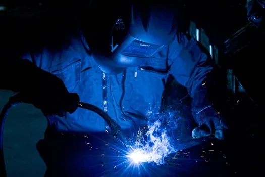
Spec sheets quote 15 m as a typical maximum operating range for a Type 4 light curtain such as the GL-S or SLC30 series, but the welding cell almost never needs anything close to this; the practical upper limit is set by spatter accumulation on the optics, not by emitter power [S5][S6].
IP67 housing is the practical minimum for any arc-welding environment because weld spatter and cooling water both reach the curtains; slimmer profiles such as the GL-S series are designed to fit inside the cell footprint where the bracket geometry would otherwise shade larger units [S4][S6].
Beyond ingress, the installation environment requires stable temperature, clean optics, and controlled background reflection; Gtekesens' installation note specifies that ambient light, vibration, and reflective surfaces must be addressed before commissioning, otherwise nuisance tripping halts the weld schedule [S3].
OSSD Outputs, Restart Logic, and Master/Slave Wiring
OSSD (Output Signal Switching Device) outputs in potential-separated semiconductor design or with monitored, compelled-connection NC contacts are the standard interface to the welding cell's safety relay, and start/restart disable plus master/slave detection are the two functions that map directly onto robotic-cell safeguarding [S5].
Master/slave cascading lets a single pair of cables run from the cell controller through the master and out to the slave curtain, simplifying the cable tray on long weld lines, while the start/restart interlock prevents automatic re-energisation of the weld power source after a curtain breach, which is mandatory when the operator must reach into the cell to clear a stuck electrode [S5].
For hazardous-area weld enclosures, ATEX zone 2 certification on the light curtain (or the use of a purged enclosure) is sometimes required; the SLC30 family is offered with this option, and this is one of the clearer differentiators versus a generic light curtain [S5].
What a Light Curtain Will Not Catch in a Weld Cell
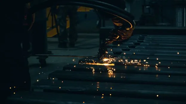
Schleich's test-station guidance is blunt: mechanical movements must stop safely within the shortest possible time, and a safety light curtain may be the wrong tool when free shafts or rotating fixtures cannot be brought to a safe state fast enough [S2].
Thin cables exiting the test bay, work-piece electrodes, and the welding torch leader can all pass between beams at 14 mm pitch and energise downstream hazards; this is why most weld cells pair the light curtain with a guarded tool changer, a mechanical interlock, or a fixed perimeter fence [S2].
For deeper coverage of perimeter guarding on sites with dust and weather exposure, see this safety light curtain selection for construction sites guide; for the bearing and conveyor subsystems that sit downstream of the weld cell, the pillow block bearing selection for packaging line conveyors piece covers similar spec-first logic.
Selection Criteria vs. Use-Case Fit
For a robotic MIG weld cell with frequent operator loading, the spec is Type 4, 30 mm resolution, IP67, OSSD outputs, start/restart interlock, ATEX zone 2 only if solvent vapour is present, and a master unit plus slave if the field height exceeds the single-cable run limit [S5][S4][S6].
For a stud-welding press or a manual TIG station where the operator's hands routinely approach the electrode, drop to 14–20 mm resolution and add a muting function tied to the weld controller so the curtain only trips when the electrode is energised [S2][S5].
For a perimeter access guard around a multi-robot weld line, single-beam through-beam pairs such as the WSU/WEU26-3 at 70 m range are more economical than a full curtain, provided the cell's risk assessment accepts a lower resolution for whole-body detection [S1].
For a Schleich-style test bay where high-voltage DUTs are exposed, a safety light curtain may be ruled out entirely if the stop time cannot be guaranteed; in that case the welding and cutting tool classification reference and the general fire-safety requirements are the appropriate guard specifications, and the curtain is replaced by interlocks plus mechanical barriers [S2].
Installation Environment: The Often-Skipped Chapter
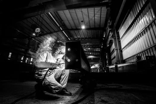
Three environmental constraints dominate the welding-cell installation: stable temperature so the LED emitter wavelength does not drift off the receiver band, clean optics because spatter and grinding dust attenuate the beam and force the device into operating-reserve faults, and EMI/UV shielding so the arc flash does not blind the receiver [S3][S5].
Mount the emitter and receiver on rigid, vibration-isolated brackets so the beam does not walk out of alignment during the welding cycle, and route the OSSD cables away from the welding secondary loop to avoid common-mode noise on the safety output [S3][S5].
For perimeter enclosures that also act as guarding, glass curtain wall and metal curtain wall panel selections should be cross-checked with the safety light curtain's mounting and reach to keep the safeguarded zone continuous; the door window curtain wall reference applies where the operator access door interrupts the curtain field.
Trackable Signals and Sourcing Notes
Vendor selection tools such as the Keyence GL-S configurator walk the engineer through main-unit type, mounting style, and feature flags before producing a parts list, which makes them useful for verifying that the final spec matches the cell drawing [S6].
Two trackable signals for spec compliance over the next quarter: type 4 OSSD light curtains with ATEX zone 2 options (such as the SLC30 family) entering more robotic weld-line retrofits [S5], and single-beam through-beam access devices (such as the WSU/WEU26-3) being specified where perimeter access replaces point-of-operation guarding [S1].