
An operator-presence safety mat is a pressure-sensitive floor device that trips a safety stop the moment a defined weight is applied to its active area, while a safety interlock switch is mounted on a guard door, hinge, or sliding panel and signals a stop only when that guard is opened.
Both are listed under functional-safety catalogues alongside safety barriers and safety fences, but their trigger mechanisms, footprint, and integration cost differ enough that the choice is set by the access geometry of the cell, not by the safety integrity level alone [S1][S3].
Trigger Principle and Active Area
A safety mat is built from two conductive plates separated by a compressible spacer; when a defined mass (commonly 25-35 kg for adult operator detection) is applied, the plates short and a 4-wire output changes state. Active area per mat is typically 250 × 500 mm up to 1000 × 1500 mm, and tiles can be fielded edge-to-edge to cover an irregular floor footprint, which is why mats are specified around robot cells where the operator must enter a defined zone to load a fixture [S1].
A safety interlock switch, by contrast, is a discrete position device: a coded or mechanical actuator enters the switch head, the internal contacts close (or open in a safety circuit), and the safety relay sees a guard-closed state. The contact block is usually rated 1 NO + 1 NC or 2 NC, with housings in glass-filled polyester, die-cast zinc, or 316L stainless for hygienic cells [S3][S4].
Where Each Device Fits and Where It Does Not
Specify a safety mat when the hazard is exposed and the operator must stand inside the danger zone to perform a task — typical applications are robot load stations, palletiser in-feed pockets, and press out-feed conveyors. Mats handle the case where the operator's hands are occupied and reaching for an e-stop is not realistic, and they pair with a safety mat controller that monitors the short-circuit, cross-fault, and open-circuit conditions that a 4-wire mat is designed to expose [S1].
Specify a safety interlock switch when the hazard is mechanically fenced and access is through a defined guard door, gate, or hatch. Guard-locking variants add a solenoid that holds the door closed until a safe stop is confirmed, which is the standard architecture for cells where stop time is longer than access time (large inertia rolls, hydraulic presses). Interlock switches are not a substitute for mats on an open hazard, and mats are not a substitute for a guard on a swing door — each fails to cover the geometry the other exists for [S3].
Selection Criteria: PL, IP, Contacts, and Coding
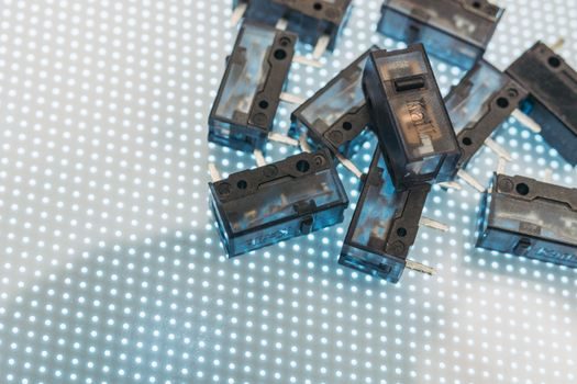
Both devices can reach PLe / SIL 3, but only with the right contact block and controller pair. For interlock switches, the relevant lever is coding level: uncoded (EN ISO 14119 Type 1) accepts any actuator and is suitable for low-manipulation hazards, while uniquely-coded (Type 4) tolerates a coded magnet up to higher mechanical defeat forces, and tamper-resistant RFID-coded heads (Type 4 / high) are specified where operator circumvention is a known risk [S1][S3].
For safety mats, the comparable lever is the controller: a single-channel mat is restricted to PL c / SIL 1 applications, a dual-channel short-circuit-monitored mat with a Category 3 controller is the floor for PL d, and Category 4 wiring plus a controller that monitors both channels for short, open, and cross-fault is required to reach PL e. The mat itself has a pressure threshold, a response time under 30 ms is typical, and the housing is specified to IP65 / IP67 for wet cells and IP69K for food-grade washdown [S1].
Contact configuration on interlock switches is usually speced as 1 NO + 1 NC for basic status, 2 NC for redundant safety, or 2 NC + 1 NO when the NO is used as a guard-position indicator back to the PLC. Operating temperature on the RS catalogue range runs from a minimum of -25 °C to a maximum of +80 °C, with hazardous-area certification (ATEX / IECEx) available on stainless and heavy-duty variants for Zone 1 and Zone 21 [S1][S4].
Comparison Table: Mat vs Interlock on the Four Decision Criteria
On trigger geometry, a mat covers an open floor area of 0.125-1.5 m² per tile and is fielded in arrays, while an interlock switch guards a single hinged or sliding guard and is a point device; on PL/SIL ceiling, both can reach PLe / SIL 3, but a mat requires a dual-channel controller with cross-fault monitoring and an interlock switch requires a coded actuator plus a safety relay that monitors both NC contacts. [S1]
On environmental rating, mats are typically IP65 / IP67 floor-encapsulated units, interlock switches in stainless reach IP67 / IP69K with hazardous-area certification; on integration cost, a mat requires a controller plus perimeter trim and a controller channel pair, while an interlock switch only needs one safety input on the relay and the wiring run to the door [S1][S3][S4].
Integration with the Safety Relay and the Control System
Both devices land on the same downstream block: a safety relay, a safety PLC, or a modular I/O card such as the ASi-Safe, EtherCAT FSoE, or PROFIsafe stacks. The safety relay must accept the device's contact or short-circuit signature, debounce it within the safety response time budget (typically under 25 ms for the relay plus mat or switch response), and drop the contactors if the loop opens. Mis-wiring a mat to a standard 24 V digital input is the most common integration fault and silently bypasses the safety function [S1].
For multi-zone cells, several mats can be paralleled into a single mat controller provided the controller has the channel count and the field wiring maintains the 4-wire short-circuit-monitored topology; for multi-door cells, each interlock switch typically gets its own input and is daisy-chained in series when the safety relay supports cross-fault monitoring across multiple contacts. The two architectures are not mutually exclusive: a robot cell with a swing guard and a load-station open area uses both, with the safety relay configured as two independent stop paths [S3].
Standards, Approvals, and the Sourcing Picture
The governing standard for both is EN ISO 13849-1 for Performance Level and EN ISO 14119 for interlock devices specifically, with EN ISO 13856-1 covering the mat side. ATEX 2014/34/EU and the IEC 60079 series govern the hazardous-area variants, and the Chinese GB 4943.1 definition of a safety interlock device mirrors the IEC 60950-1 / IEC 62368-1 transition path that most safety switches and mat controllers are tested against on the Asian supply side [S1][S3][S6].
On sourcing, RS Components lists 3,362 safety interlock switch products on its UK catalogue page as of 2026-06-03, with brand coverage spanning IDEM, Schmersal, Euchner, Sick, and Rockwell — see the IDEM filter page for a typical sub-vendor view [S1][S3][S4]. For mat sourcing, expect longer lead time on IP69K hygienic variants and on RFID-coded interlock heads; the typical un-coded interlock switch and standard mat controller remain stock items, and the published China import-tariff data set for "safety interlock selector switch" remains a useful cross-check for landed-cost work on the Asian supply side [S5].
Failure Modes and What the Specification Must Catch
Mat failure modes are dominated by mechanical damage: punctures, cuts from forklift traffic, and edge-lift where the trim is improperly anchored, each of which can either short the mat permanently (false trip) or create an open circuit (bypass). The controller's short-circuit and cross-fault monitoring is the only line of defence against a bypass, which is why a single-channel mat is restricted to lower PL levels and why the dual-channel topology is the default for new builds [S1].
Interlock switch failure modes are dominated by actuator defeat: the operator wedges the actuator closed, uses a substitute object to hold the contacts in, or simply fails to close the door. A coded or RFID actuator is the design lever, and the safety relay's cross-fault monitoring handles contact welding. Both devices share a common gotcha — the safety function can be silently defeated by wiring a jumper across the contacts, which is why lockable disconnect, guarded cable runs, and a documented commissioning checklist are the spec items that prevent this in the field [S1][S3].
Track these as next signals when you revisit the spec in 6-12 months: (1) the EN ISO 14119 maintenance amendment activity, which historically tightens the defeat-resistance requirements for coded actuators, and (2) the China import-tariff movement on safety interlock selector switch HTS lines, which has been the most visible landed-cost signal on the Asian supply side in the past 12 months [S5].
For related coverage, see Gravity Die Casting Machine Suppliers 2026: China Cluster Map, Spec Bands and Sourcing.