
A high-torque timing-belt drive needs controlled tension, not simply a tight belt: excessive preload overloads bearings and cords, while insufficient preload can cause tooth jumping at startup [S4][S5].
Match the tensioner to the belt section, tooth profile, pulley geometry, peak torque, shaft layout, and required take-up travel; high-torque applications generally favor HTD-style tooth geometry and a wide belt rather than a narrow, lightly loaded drive [S1][S3].
Choose HTD or another timing-belt profile
HTD teeth use a curvilinear profile intended to carry higher torque and load capacity than conventional trapezoidal forms, making HTD a sensible starting point for a high-torque drive [S1]. The relevant belt sections include HTD 5, HTD 8, and HTD 14, with nominal pitches of 5 mm, 8 mm, and 14 mm respectively [S3].
The timing belt must match the timing pulley tooth form. Tooth profiles are not uniformly interchangeable between manufacturers, and mixing incompatible belt and pulley forms can lead to poor engagement [S5]. Replacing a pulley with one having a different tooth count also changes the speed ratio and the required center distance, which changes the required belt length [S5].
Do not select an HTD belt merely because its catalogue rating is high. Confirm that the complete drive, including reinforcement, width, number of teeth in mesh, pulley count, center distance, and service factor, has been sized by the belt manufacturer. Gates distinguishes power transmission from conveying and linear positioning because the loading geometry differs substantially between those applications [S3].
Set the tensioner load from the drive duty
Calculate the drive-side and slack-side tensions from peak torque rather than from nominal motor rating. Design tension is commonly expressed as the ratio of drive-side tension to slack-side tension, together with a wedging factor for V-belts; the same operating principle requires enough slack-side tension for positive tooth engagement [S2].
A belt tensioner must react the shaft load generated by the belt without imposing unnecessary radial load on the driven shaft. At startup, peak transmitted torque can be several times the steady torque depending on motor acceleration, load inertia, and drive geometry, so the tensioner and its fastener should be checked against that peak case rather than a nominal-load case [S2][S3].
For a fixed-center drive, the tensioner must supply the adjustment needed to install the correct belt length and then hold working tension without allowing slack-side tension to collapse. For a center-distance adjustment problem, use the specified belt-length formula rather than selecting an oversized long belt and leaving it loose [S3]. The tensioner arm should also provide enough travel for wear compensation, as detailed in Belt Tensioner Arm Travel for Stretch Compensation.
Compare tensioner mechanisms against four criteria
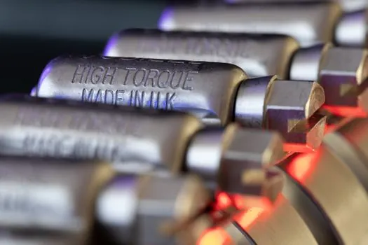
For most high-torque drives, compare four mechanisms using installation control, load capacity, maintenance, and contamination sensitivity. The tensioner mechanism matters less than the resulting belt preload and bearing reaction, provided the drive remains aligned [S2][S4].
A screw or fixed adjustable idler is a poor choice for a remote, inaccessible high-torque drive because tension checks become dependent on maintenance access. A spring or hydraulic unit is more appropriate where automatic compensation or stable preload is required, but neither compensates for pulley misalignment or incorrect belt length [S4][S5].
Specify the idler and its mounting hardware
Select an idler diameter large enough to avoid excessive bending stress, and confirm that the belt section is approved for that diameter by the belt manufacturer. The available HTD belt and pulley range includes 5, 8, and 14 mm pitches, but pitch alone does not determine the acceptable minimum pulley diameter or the permissible tensioner contact [S1][S3].
An idler used inside the belt loop should have flanges to retain the belt where lateral tracking forces are credible. A backside idler requires adequate belt-back clearance and must not contact a tooth or unsupported edge. Material choice should account for belt cover compatibility, contamination, temperature, and the risk of edge cutting. The trade-off between steel and composite idlers is covered in Steel vs Composite Tensioner Pulleys for Belt Wear.
Specify the idler bore, mounting fasteners, and bearing arrangement as a single load path. Bearing seals should suit the actual environment, while the fastener and arm must be sized for the belt reaction rather than the idler diameter alone. The detailed bore and seal decision is addressed in Specify Tensioner Pulley Bore and Bearing Seal Type.
Control belt tension by measurement
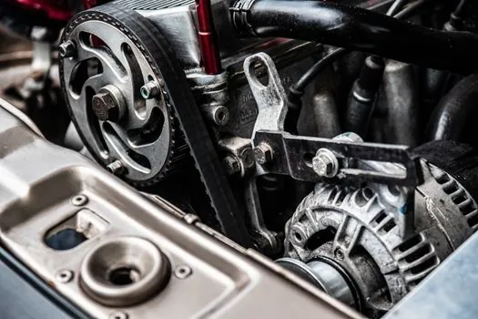
Set tension by the span-deflection method rather than by appearance. The installation instruction specifies a belt deflection of 1/64 inch for every inch of span under a specified force [S4]. For a 50-inch span, the corresponding deflection is 50/64 inch, or 25/32 inch [S4].
For belts wider than two inches, S4 specifies placing a metal or wooden strip 3/4 to 1 inch wide across the belt between it and the tester to prevent distortion, and it identifies a table of normally adequate deflection forces without providing the table values in the supplied excerpt. These values are installation checks, not substitutes for manufacturer sizing, because actual tension depends on peak load, system rigidity, and the number of teeth in mesh [S4].
For belts wider than 2 inches, the instruction calls for a metal or wooden strip 3/4–1 inch wide between the belt and the measuring device to prevent distortion [S4]. Measure after the belt is seated and the take-up has removed slack, and check both the drive and idle shafts before locking the mechanism.
Limit alignment, installation damage, and contamination
Parallel and angular misalignment increase tracking force, uneven tooth wear, noise, uneven load distribution, and tensile-cord failure [S5]. Angular misalignment overloads cords on the tight side, so it can progress from edge-cord damage to failure across the belt width [S5].
The installation guideline states that drive misalignment should be less than 1/4 degree or 1/16 inch per foot of linear distance [S5]. Use that as an installation limit and check it with a straightedge or dial indicator before final tension adjustment. Misalignment reduces belt life in a way that is not accounted for by normal drive-design calculations [S5].
Never pry a timing belt over a pulley, because the levering action can damage the pulley teeth or flange; force-fitting a belt can crack internal tensile cords [S5]. Clean pulleys with a lightly dampened rag and a light, non-volatile solvent, then allow belt and pulleys to dry before assembly. Sharp scraping tools can damage the belt cover, and solvent should not be brushed or soaked into the belt [S5].
Verify the final tensioner specification
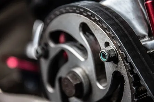
The purchase specification should state the belt profile and pitch, belt width, tooth count, pulley tooth count, rated power, peak torque, center distance, idler diameter, idler width, flange arrangement, shaft or arm material, bore, bearing seal, mounting fastener grade, adjustment range, required belt tension, and alignment tolerance. Record the measured installation span and deflection force so maintenance can reproduce the specified setup [S4].
Reject a tensioner package when the idler has no documented minimum pulley-diameter approval, the bearing reaction is omitted, the belt tension cannot be measured, or the fastener is selected without the calculated belt reaction. Validate the assembled drive at startup with the driven machine disconnected where practical, then inspect tooth engagement, noise, edge wear, and pulley tracking under load.
For the shortlist, choose an HTD belt and matching pulleys for high-torque tooth engagement, a flanged idler or back-side idler with approved clearance, and the simplest tensioner mechanism that maintains the calculated preload through the required service life. Track two verification signals after commissioning: measured span deflection at the specified force and angular alignment below the 1/4-degree installation limit [S5].