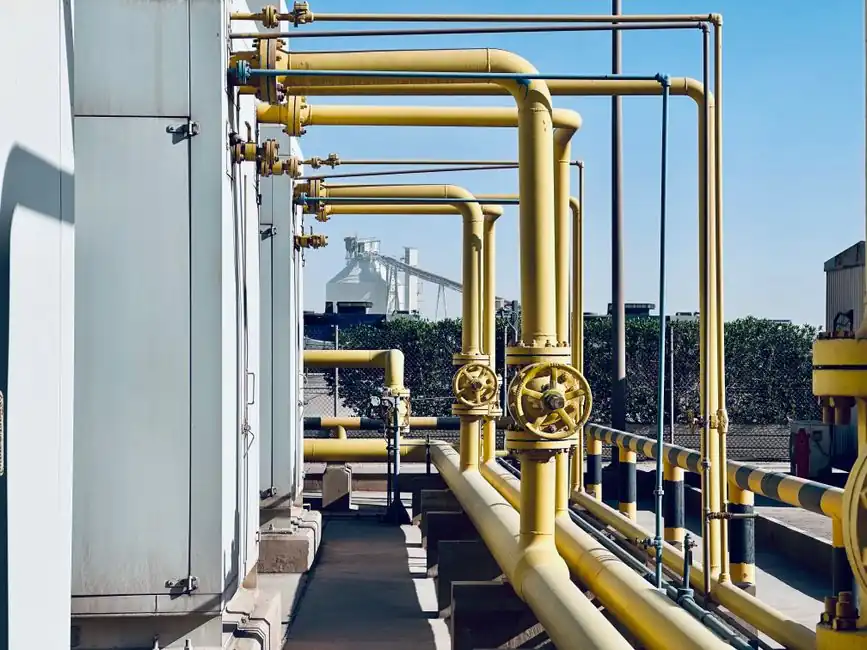
A safety relief valve for water treatment must open at the selected set pressure, deliver the calculated relieving capacity at the permitted overpressure, and reseat after the protected system returns to a safe pressure.
The correct choice depends on whether the medium is clean or treated water, whether the relief case is liquid, gas, or mixed-phase, and whether installation is on a vessel, pump, filter housing, membrane system, or closed hydronic loop.
Define the overpressure scenario before selecting the valve
A pressure relief valve is a final protection device for vessels, piping, and systems exposed to overpressure; it is not a substitute for a control or regulating valve [S2]. The sizing input must therefore include the maximum allowable working pressure, accumulated or non-accumulated overpressure, required set pressure, required relieving capacity, back pressure, and the fluid state at discharge [S5].
For liquid water service, a relief valve opens progressively as pressure rises above its set point and modulates its opening as flow follows the overpressure. This behavior suits incompressible liquid service and reduces the likelihood of abrupt operating cycles [S3]. A safety valve uses rapid pop action for compressible service, while a safety relief valve is capable of serving liquid, gas, or steam duty [S3].
Do not assign a relief device until the credible overpressure case has been defined. A common failure mode is selecting for normal operating pressure rather than the emergency condition that produces the required flow [S7]. The protected equipment’s MAWP, the allowable overpressure for that equipment, and any operating-pressure limits all belong in the sizing basis [S2][S5].
Match valve behavior to the protected system
Liquid service generally calls for gradual opening, while gas or steam service calls for rapid full-lift opening; a combined safety relief valve covers applications in which either behavior can be required [S3]. This distinction is more than terminology because a valve with the wrong opening characteristic can chatter, wear its seat prematurely, or fail to provide the required rapid discharge [S3].
A pressure relief valve is intended to protect life and property by venting fluid from over-pressurized equipment [S2]. It must open at a predetermined set pressure, provide rated capacity at a specified overpressure, and close when system pressure returns to a safe level [S2]. The installation and internal geometry must also allow stable operation over the expected pressure range, fluid phase, and flow conditions [S5].
Do not use a safety valve as the default answer for a water system. For water distribution, pump-discharge protection, liquid equipment, and hydronic service, progressive liquid behavior is normally the correct starting point [S3]. Conversely, a progressive valve is a poor choice where the governing demand is immediate full-capacity discharge of a compressible fluid [S3].
Calculate relieving capacity from the governing case
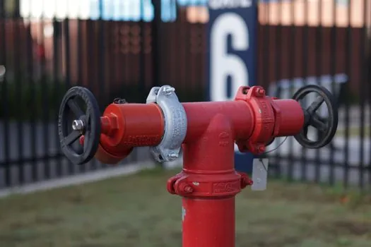
Sizing begins with required relieving capacity, followed by set-pressure selection, identification of the applicable sizing equation, and capacity verification [S7]. For water treatment, the calculation must also identify whether the demand is caused by blocked-in liquid, thermal expansion, compressor or pump failure, filter blockage, membrane-system upset, or another credible overpressure source.
At least 3 inputs must be reconciled before purchasing: set pressure, allowable overpressure, and required capacity. Additional installation inputs include back pressure, fluid density, fluid compressibility, inlet and outlet losses, and the temperature at the valve [S5]. If the discharge system cannot carry the calculated capacity at the available back pressure, the selected valve may not achieve its rated performance even when its nameplate capacity is correct.
The valve must also be verified for the expected operating range, including pressure transients, fluid viscosity, and whether gas bubbles or two-phase flow can occur [S5]. A clean-water calculation does not automatically cover an aerated feed, a chemical cleaning step, or a mixed-phase relief case. Water-treatment applications should not use the general valve-selection guidance for isolation and throttling as a substitute for pressure-relief sizing [S4].
Check materials, inlet conditions, and discharge system
Relief-valve materials must be compatible with the process fluid, ranging from air and water to corrosive media [S2]. Water treatment plants use valves to regulate flow, pressure, and fluid isolation, with different valve types selected for their specific roles [S4].
Installation envelope is a design constraint, not a secondary commercial issue. Valve location, available inlet and outlet piping, support, access for inspection, and discharge routing influence selection and installation [S6]. The inlet and outlet arrangements must also account for flow dynamics, pressure drop, abrupt pressure fluctuations, and acoustic resonance identified as concerns in PSV design review [S5].
A discharge pipe must not create an uncontrolled restriction or another protected equipment item. The full relieving condition must be evaluated through the actual discharge system, including piping diameter, length, bends, elevation, and outlet condition. Conversely, the discharge arrangement must protect personnel and the environment because relief operation can release a substantial water load [S2].
Use water-treatment controls for their actual duties
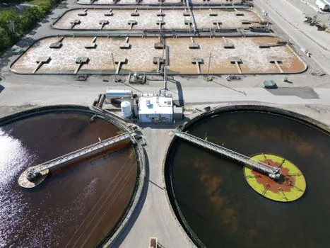
Water-treatment plants require distinct devices for distinct functions: gate valves provide isolation, globe valves support throttling, and control valves regulate flow, pressure, or temperature [S4]. None performs the final overpressure-protection function specified for a relief valve [S2]. In a properly engineered system, the control valve reduces the probability of an upset, while the safety relief valve protects against the credible failure that remains.
For example, a pump discharge may require a relief device sized for the runout condition with the discharge valve blocked. A closed chilled-water system may also face expansion-related overpressure, requiring a relief path sized for the calculated thermal expansion rate [S9]. A filter or membrane housing requires analysis of blocked outlet or loss of containment rather than a generic “filter vessel” selection.
Where a gas or mixed-phase relief case exists, consider a pressure vacuum relief valve only when vacuum protection is a documented design requirement. It is not a substitute for the positive-pressure relief device required to protect piping and vessels from overpressure.
Apply the governing code and procurement documentation
Pressure-relief selection for pressure vessels should be aligned with ASME BPVC Section VIII, Division 1, and sizing practice based on API Recommended Practice 520, as reflected in the supplied course material [S2]. For power-boiler service, ASME BPVC Section I governs, while ASME PTC 25 covers performance testing of pressure-relieving devices [S3]. The applicable code depends on the protected equipment and jurisdiction, not on the product label alone.
ASME defines pressure relief valves, safety valves, and safety relief valves within the Boiler and Pressure Vessel Code framework [S3]. National Board jurisdiction can also affect installed pressure-relieving devices [S3]. The purchase specification should identify the governing code, edition used by the project, service fluid, design pressure, MAWP, set pressure, allowable overpressure, required capacity, back pressure, operating temperature, materials, allowable pressure drop, inspection or test requirements, and discharge design.
Installation, maintenance, and testing remain part of the safety case. The 2023 review by Bhowmik and colleagues identifies sizing, selection, installation, maintenance, and testing as the core elements of reliable PSV use [S5]. For procurement, require certified capacity data and documented limits rather than accepting a generic “water service” catalog entry.
Build a shortlist from the operating envelope

A water-treatment SRV shortlist should be approved only when 5 items are explicit: the credible overpressure case, calculated capacity, allowable overpressure, installation back pressure, and compatible wetted materials. The main selection comparison is progressive liquid relief for ordinary water systems, combined safety relief service where liquid and compressible contingencies exist, and pop-action safety service for compressible media. [S2]
Reject the mainstream liquid relief valve when the calculated case requires immediate full-lift gas or steam capacity, when discharge back pressure exceeds the certified limit, or when the fluid chemistry is incompatible with the selected trim and body materials. Reject a pop-action safety valve for ordinary liquid service when progressive action, stable reseating, and reduced liquid-service chatter are the governing requirements [S3].
Before release, verify the final valve data against the protected equipment MAWP, the approved pressure-relief calculation, the piping-system model, and the applicable code edition. Then record set pressure, capacity, back-pressure limits, temperature limits, materials, test requirements, and installation constraints in the procurement dossier [S1][S5][S6].
The trackable acceptance signals are a calculation package showing required capacity at the design overpressure and a certified valve selection matching the actual system envelope, including inlet and discharge conditions.