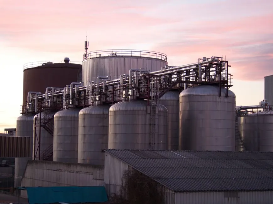
A chemical-process safety relief valve must open at the selected set pressure, deliver the calculated relieving capacity at the permitted overpressure, and close after the protected system returns to a safe pressure [S3][S4].
Selection applies to reactors, vessels, columns, exchangers, solvent systems and utility skids, but the governing relief scenario, fluid phase, temperature, back pressure and chemical compatibility determine the final valve configuration [S4][S5].
Start with the governing overpressure case
Blocked outlet, reaction upset, gas generation, thermal expansion and tube rupture produce different discharge loads, so a single generic PSV selection is unsafe. Chemical processing overpressure can arise from reaction, heating, vapor generation, blocked flow, external fire, tube rupture, regulator failure or trapped-liquid expansion [S5].
For a blocked outlet, feed continues while downstream flow falls to zero. For an exothermic batch reaction, evaluate reaction heat, gas-generation rate, solvent vaporization, foaming and possible two-phase discharge [S5]. A thermal scenario includes trapped liquid between closed valves, while a heat-exchanger duty can involve tube rupture, blocked cooling, steam-side upset or hot-oil expansion [S5].
The selected capacity must cover the credible governing case rather than an average operating condition. Relief sizing begins with set pressure, back pressure, allowable overpressure and required relieving capacity, while set pressure is established from operating pressure and the applicable equipment limits [S3][S4].
Match the valve type to control and protection needs
A conventional safety relief valve is spring-loaded, opens rapidly at its set pressure and cycles between fully open and fully closed; a proportional relief valve opens gradually as pressure moves away from its setpoint [S3][S4].
For the first selection pass, compare conventional PSVs, proportional PRVs and thermal relief valves against four criteria: rapid emergency action, gradual modulation, liquid-expansion duty and certification basis. Conventional PSVs suit overpressure protection, proportional PRVs suit controlled pressure relief, and thermal relief valves address liquid expansion rather than gas or vapor overpressure [S1][S4][S5].
Size for capacity, gas or liquid, and two-phase flow
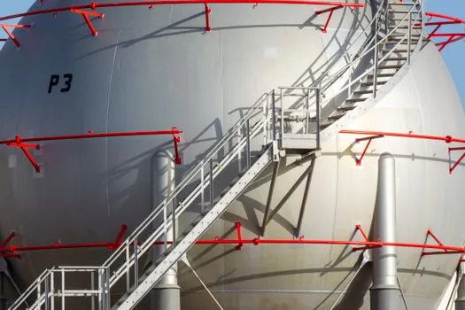
Relieving capacity must be calculated for the governing scenario, with separate treatment for compressible gas, incompressible liquid and mixed-phase discharge. Chemical service can produce vapor, gas, foam or liquid carryover, and batch reaction calculations must include heat release, gas generation and solvent vaporization [S4][S5].
The sizing process is governed by set pressure, back pressure, allowable overpressure and rated capacity [S4]. The course outline covers codes and standards, equation nomenclature, selection and sizing, a summary, additional resources, a glossary, and references [S3].
Inlet and outlet piping can change valve performance. High-pressure application guidance identifies inlet and outlet geometry, abrupt pressure fluctuations, gas-bubble formation and collapse, pressure drop, acoustic resonance and multiphase behavior as issues that must be considered during sizing, installation, testing and maintenance [S4].
Set operating limits for each protected segment
Each protected segment needs its own allowable pressure basis, and the relief valve must be set no higher than that allowable limit. A relief valve is not a process regulator, does not replace a control valve, and must open at a predetermined set pressure, deliver rated capacity at a specified overpressure, then close at a safe system pressure [S3].
Install protection at critical points during system design, rather than adding it after pressure transients appear. Toxic media may require a captured discharge, while air or nitrogen can be released in accordance with the plant hazard assessment [S1][S2]. The safety relief valve therefore belongs to a defined protected system, set-pressure limit and discharge route.
For vacuum-protected or alternately pressurized systems, review whether the actual duty is overpressure, vacuum protection or both. Chemical service lists vacuum protection alongside steam, water, chilled water, nitrogen and small gas skids, confirming that a conventional PSV is not automatically the correct device for every pressure hazard [S5]. A pressure-vacuum relief valve is relevant where both pressure directions require protection.
Verify chemical compatibility and discharge consequences
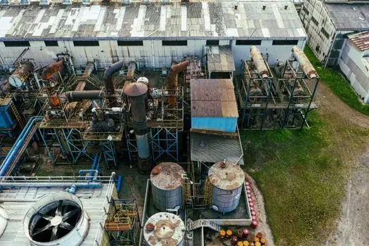
Material selection covers the body, trim, spring, seat and discharge path, not only the wetted body material. Chemical-processing safety valves are used for corrosive, reactive, and utility systems, including acid and alkali service, and the correct PSV or PRV depends on chemical compatibility and material compatibility [S5].
Corrosion is not the only selection constraint. Other service risks include crystallization, toxic vapor, solvent vapor and sticky media, while thermal duties require checks of temperature rating, pressure differential and discharge routing together [S5]. Spring selection and trim geometry also affect operation, so a compatible body with an unsuitable spring or seat does not provide a valid selection.
For solvent and VOC systems, review flammability, vapor pressure, static-electricity controls and closed-discharge routing [S5]. For gas releases, account for discharge-system back pressure and possible interaction with the air-release valve used elsewhere in the vent system, but do not treat air release as a substitute for required overpressure capacity.
Separate PSVs from control and isolation duties
A safety relief valve is a fail-safe device that uses process-fluid energy and must operate even during a power failure [S3]. Proportional behavior does not make a PRV equivalent to a control valve, because the PRV opens gradually and may remain partially open, whereas the PSV provides rapid emergency action [S4].
Chemical process control valves, diaphragm valves and isolation valves solve different duties from overpressure protection. The selection guide for chemical process control valves by service and sizing helps separate normal throttling from emergency pressure relief; it does not replace PSV sizing calculations or installation checks.
Do not use a proportional PRV as the mainstream answer when rapid, full-capacity emergency venting is required. Its graduated opening and possible partial-open operation are different operating characteristics from the full-open, full-close cycle expected from a conventional PSV [S4].
Specify procurement, testing, and documentation

Specify the selected set pressure, fluid phase, design temperature, relieving-capacity basis, allowable overpressure, inlet and outlet pressure conditions, discharge destination and governing relief scenario [S3][S5]. For chemical service, the RFQ record should also state material compatibility, capacity calculations, seat-tightness requirements and required test documentation [S5].
Relief valves must be selected, sized, manufactured, assembled, tested, installed and maintained as part of the complete protection system [S3]. High-pressure guidance adds that servicing and testing must account for multiphase flow, boundary-layer formation, pressure drops, gas-bubble behavior, abrupt fluctuations and acoustic resonance [S4].
The final shortlist should contain one valve for the established governing case, one acceptable alternative only if it satisfies the same capacity and operating criteria, and a separate thermal-relief option where trapped-liquid expansion governs. Require confirmation of set pressure, capacity, temperature, back pressure, material compatibility, piping influence, discharge routing and test scope before releasing the valve for installation [S3][S4][S5].