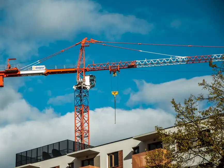
Tower crane selection on a high-rise job collapses to four numbers: maximum single-lift weight, jib radius, finished roof height plus 6-10 m of hook clearance, and the available site footprint for the base or tie-in [S4][S9]. Get any of those four wrong and the crane either cannot place the heaviest prefabricated element on the plan, cannot clear the structure, or simply cannot be erected on the plot.
For practical high-rise work the field divides into three regimes. Free-standing hammerhead and flat-top cranes cover buildings up to roughly 265 ft (80 m) above the base, relying only on a concrete foundation and ballast [S3][S7]. Above that, the mast is tied into the structure with steel braces spaced every 65-100 ft (20-30 m), and tied-in configurations have reached over 1,000 ft (305 m) of vertical service [S3]. On the tightest urban cores, the crane is set up inside the elevator shaft and climbs with the building on hydraulic jacks, leaving no external footprint at all [S3][S4].
Four Crane Types and the Sites They Actually Fit
Hammerhead (saddle-jib), flat-top, luffing-jib, and self-erecting are the four procurement categories a spec engineer chooses between, and the decision is driven by airspace, congestion, and lift weight rather than height alone [S1][S8]. Hammerhead cranes carry a fixed horizontal jib with a trolley and a tower-top pendant system; they are the heavy-lift workhorse on open sites where the radius can swing freely [S1][S2]. Flat-top cranes are hammerheads with the tower-top cap and pendant lines removed, giving a lower head profile that is preferred when several cranes share overhead airspace on a single site [S1][S2]. Luffing-jib cranes replace the fixed arm with a jib that raises and lowers to change reach, trading working radius for the ability to work between adjacent structures and other tower cranes [S1][S2]. Self-erecting cranes are small hydraulic units that unfold without a separate assist crane and are reserved for short-cycle or residential work, not for true high-rise cores [S1][S2].
For dense urban high-rise projects, luffing-jib and flat-top are usually the only two configurations that survive a site logistics review. Hammerhead jibs need full 360° swing clearance and their pendant lines impose a headroom envelope that collides with neighbouring tower cranes; flat-top removes the pendant envelope, luffing-jib removes the swing conflict by varying the jib angle [S1][S6]. On a typical 40-60 storey core, contractors frequently run a luffing-jib inside the building footprint and one or more flat-tops on the perimeter to cover the deck, since each luffing-jib can lift very heavy loads to great heights without crossing a neighbour's airspace [S2][S6].
The Four Numbers That Drive the Spec Sheet
Procurement starts by quantifying the worst-case lift, the working radius to the worst-case lift, the under-hook height, and the mast or tie-in configuration that gets the crane there [S4][S5][S9]. The maximum lifting capacity is set by the single heaviest element on the plan, including the rigging and any spreader beam, not by the average daily pour weight [S4][S5]. The working radius for a horizontal-jib crane is the horizontal distance from the mast centre to the farthest pick point on the building, normally taken from the diagonal of the floor plate; for a luffing-jib unit it is the projected length of the boom at the working angle [S4]. The under-hook height must be 6-10 m above the highest finished structural point so slings, blocks, and the operator's lift cycle clear rebar, formwork, and the safety screen on the top deck [S4].
Free height and maximum height are separate parameters and must be read off the manufacturer's load chart, not estimated. Typical low-cost flat-top procurement brackets sit in the 48-60 m radius / 4-6 t class / 32-40 m free-height range, mid-range brackets at 60-65 m / 8-10 t / 40-60 m, and heavy-lift brackets at 65-75 m / 10-16 t / 44-60 m, with unit price scaling roughly two to three times from the low to the heavy bracket [S4]. These are ballpark class brackets, not model-specific quotes, and the final pick depends on the manufacturer's load chart at the required radius and height, which has to be re-read every time mast sections are added [S3][S4].
Free-Standing, Tied-In, or Internal Climbing
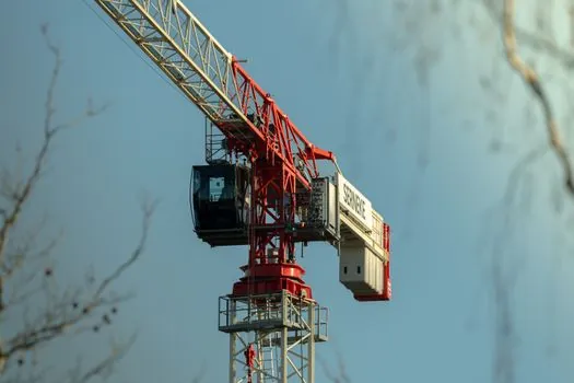
The installation method is a separate decision from crane type, and it is the one that fixes how high the crane can actually serve [S3][S4]. A stationary, free-standing tower crane sits on a prefabricated concrete foundation outside the building, climbs by adding mast sections, and is the cheapest configuration when the plot allows it and the finished roof is under about 80 m [S3][S4]. A tied-in crane uses steel braces that anchor the mast to the building at regular intervals, typically every 20-30 m, transferring lateral load into the structure and pushing service height past 300 m on projects like the Burj Khalifa and The Shard [S3]. An internal climbing crane is erected inside the elevator shaft or service core, sits on a suspended base once free-standing height is exceeded, and climbs floor-by-floor on hydraulic jacks and guide rails, leaving the surrounding site completely clear of crane infrastructure [S3][S4].
Wind load, load-chart recalibration, and counterweight adjustment are the recurring reasons tied-in and internal-climbing cranes are not just "taller free-standing cranes" [S3]. At higher altitudes wind pressure on the jib and counter-jib rises, the load chart at the new height is materially different from the chart at ground level, and the centre of gravity shifts as the building's mass is engaged through the ties. Every addition of mast section, every tie-in collar, and every climb cycle has to be matched to a manufacturer-issued chart revision; operating past the named maximum freestanding or tied-in height is treated as a structural safety event, not a paperwork event [S3].
Comparison of the Four Crane Types Against Project Criteria
The cleanest way to compare hammerhead, flat-top, luffing-jib, and self-erecting units for a given high-rise project is to score them on four criteria that map directly to procurement decisions: heavy-lift capacity, site footprint and airspace, maximum practical service height, and erection/dismantling effort [S1][S2][S6]. Hammerhead scores highest on heavy-lift capacity at long radius but needs the largest open footprint and full 360° jib clearance, and is usually specified only on sites with no neighbour-crane conflict [S1]. Flat-top matches hammerhead on capacity for a similar model class while dropping the pendant head, which is why it is the default for sites with two or more cranes sharing overhead airspace [S1][S2]. Luffing-jib sacrifices a portion of working radius for the ability to swing the load between adjacent buildings, so it is the first choice on tight urban plots and the most common pick for a single crane on a mid- to high-rise urban core [S1][S2][S6]. Self-erecting trades all of the above for fast, assist-crane-free setup, and is not used as the primary lift on a true high-rise; it is more often deployed on low-rise residential or as a secondary unit feeding a luffing-jib on the main tower [S1][S2].
Service height comparison falls out the same way. Hammerhead and flat-top both serve the full 80 m free-standing envelope and can climb higher with ties, but the operational head height of a hammerhead is taller because of the pendant system, which on tight sites counts against it [S1][S3]. Luffing-jib is commonly paired with internal climbing on the very tallest projects, since the lower head profile plus the in-shaft footprint removes both the airspace and the external-base conflicts that stop a hammerhead working at the top of a 300 m+ core [S2][S3].
What the Sourcing Records and Standards Actually Require

Procurement should not be driven by marketing claims of "maximum height" or "maximum capacity" without the underlying chart [S1][S3]. Each crane carries a manufacturer-defined maximum freestanding height, a maximum tied-in height, and a load chart that is reissued for every mast configuration; the operating limit at any given radius and height is the chart value, not a brochure number [S3]. The structural and assembly references in the public domain treat wind load, anchor spacing, and counterweight adjustment as binding design variables rather than suggestions, and the dismantling of a tall crane typically requires a smaller derrick crane staged on the roof to remove the main unit, which is itself a design input on the top-deck plan [S3].
For sites that handle hot-metal or process-plant lifts alongside the structural work, the same mast and trolley assemblies are sometimes cross-referenced with general lifting and rigging documentation used for adjacent scopes. The mast sections themselves are commonly specified in 1.2×1.2 m, 1.6×1.6 m, and 2.0×2.0 m cross-sections, with fixed-type sections chosen for cost where transport is easy and split-type sections chosen where road or site access limits section length [S4]. For procurement engineers who also handle process equipment on the same project, related lifting and process-piping decisions are covered in adjacent references such as PE pipe selection for industrial facilities and adhesive selection for dissimilar metals, and long-span gantry options for material-handling yards are discussed in why long-span gantry cranes use one flexible hinged leg.
To track what changes next, watch two signals: manufacturer load-chart revisions tied to higher wind-class regions, which directly move the maximum freestanding envelope above 80 m, and any update to tied-in anchor spacing guidance, which has been converging toward the 20-30 m band on tall cores [S3]. Project engineers can also use a tower crane reference page to keep crane-class terminology aligned with procurement documents.
For component-level specifications, see height gauge, and high voltage tester.