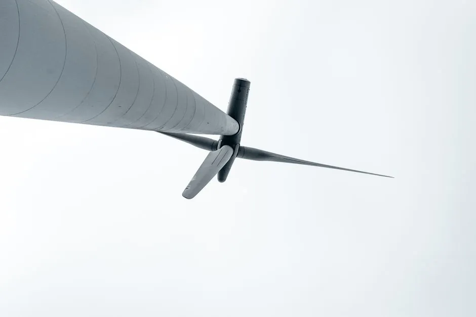
For utility-scale wind turbines in the 1.5–8 MW class, the main shaft, gearbox planetary/intermediate stages, and yaw/pitch drives are routinely specified with self-aligning bearings, spherical roller types for the main shaft where radial loads exceed 1 MN, and double-row self-aligning ball types for pitch and yaw bearings where the load is lighter and the misalignment is wider [S2].
The defining engineering advantage is the spherical outer raceway, which lets the inner ring, balls or rollers, and cage swivel up to roughly 2.5–3° for self-aligning ball bearings and 1.5–2.5° for spherical roller bearings, absorbing shaft deflection from rotor overhang, gearbox housing flex, and tower sway without inducing edge loading on the raceway [S2].
Why Wind Turbines Need Self-Aligning Capability
Wind turbine rotors impose continuously reversing radial and axial loads on the main shaft as the blade passes the tower shadow, and the gearbox input torque reacts against a housing that flexes 0.1–0.5 mm under transients, conditions where a conventional cylindrical or tapered roller bearing will fail prematurely from edge stress [S2]. A self-aligning bearing's spherical outer race lets the inner assembly pivot with that deflection, keeping the Hertzian contact patch centred and avoiding the brinelling and false-brinelling modes that drive unplanned gearbox replacements [S2].
IEC 61400-1 design load cases (DLC 1.2 extreme operating gust, DLC 2.3 parked extreme wind, DLC 6.1 emergency stop) stack these transients into the bearing L10 life calculation, and the bearing suppliers' catalogues (NSK, SKF, FAG, Timken) all present dedicated wind-industry selection tables where the spherical roller bearing is the default L10 ≥ 175,000 h choice for the main shaft above roughly 1.5 MW [S2].
Spherical Roller vs Self-Aligning Ball: Selection Matrix
Spherical roller bearings (e.g. 222xx, 223xx, 230xx CC/W33 series) carry the main shaft on most multi-megawatt turbines because they accept combined radial loads up to several MN and moderate axial loads in either direction, with a self-aligning angle of 1.5–2.5° depending on series and clearance group [S2]. Self-aligning ball bearings (e.g. 12xx, 13xx, 22xx, 23xx series) handle lighter radial loads with somewhat higher speed capability and a wider self-aligning angle of 2.5–3°, which is why they are used in pitch and yaw drives rather than on the main shaft [S2].
For wind pitch and yaw slewing rings, the bearing is effectively a custom large-diameter four-point contact or crossed roller design, but the same self-aligning principle is invoked by specifying a crowned or profiled raceway, with ISO 492 radial runout limits (Normal, P6, P5) tightening as rotor size increases [S2]. A practical decision matrix used by wind-farm O&M teams: main shaft above 1 MW, spherical roller (222xx/223xx, W33 groove + 3-lip seal); pitch drive, self-aligning ball (12xx/13xx with 2RS or 2Z seals); yaw drive, self-aligning ball or CARB toroidal depending on axial/radial mix; generator side, cylindrical roller (NU/NJ) with separate thrust bearing, since self-aligning types are not the best fit for pure high-speed radial load.
Cage, Clearance, Lubrication, and Sealing

Wind-turbine self-aligning bearings are almost universally specified with a machined brass or steel cage rather than pressed steel, because the continuous vibration spectrum and temperature swings (–30°C to +60°C ambient, with bearing bulk up to 110°C) cause pressed-steel cages to crack within 5–7 years [S2]. C3 or C4 radial clearance is the default in cold-start sites (Nordic, inner Mongolia, Canadian prairies) where differential thermal contraction between shaft and housing would otherwise preload a Normal-clearance bearing to failure.
Sealing is the dominant reliability lever. On the main shaft, 2-lip or 3-lip nitrile-rubber seals with a W33 lubrication groove and six or eight equispaced relubrication holes are now the minimum standard, with many operators moving to hybrid seals (NBR plus PTFE aux lip) for offshore turbines where salt-spray contamination drives premature grease degradation. Grease selection follows the bearing maker's wind-sector list: lithium-complex or polyurea thickener, ISO VG 100–220 base, with EP additives, re-grease interval typically 3,000–6,000 h aligned to the gearbox oil change.
Failure Modes Specific to Wind Service
The four dominant failure modes seen in wind-turbine self-aligning bearings are: (1) white etching cracks from electrical current passage through the bearing, especially on VFD-driven pitch and yaw motors, mitigated by insulated outer rings or shaft grounding rings; (2) false brinelling under parked vibration, mitigated by rotor-locking procedures and grease film thickness monitoring; (3) grease purge from over-pressurised housings, mitigated by vented end-caps and grease-escape channels in the housing; (4) roller skidding in spherical roller bearings at low speed/high load, mitigated by maintaining a minimum load ratio (typically C0/P ≥ 0.1) and selecting E or CC design rollers with optimised crowning [S2].
For more on how self-aligning bearings behave under harsh contamination and washdown in food plants, the spec map in Self-Aligning Bearing Selection for Food Processing covers sealing and lubrication parallels, and Self-Aligning Bearing Selection for Cement Plants: 2026 Spec Map carries the heavy-contamination comparison from a different load regime.
Sourcing, Standards, and Verification

Specifying engineers should anchor wind-turbine self-aligning bearing orders to ISO 492 (radial bearings, tolerances), ISO 199 (cone sleeves, adapter assemblies), ISO 15 (boundary dimensions), and IEC 61400-1 (design load cases), with material cleanliness to ASTM E45 method A and steel-grade traceability per EN 10083 or maker equivalent [S2]. Suppliers on the wind-sector short list (NSK, SKF, FAG/Schaeffler, Timken, NTN) all publish wind-specific L10 calculation workbooks that accept torque, overhung weight, and DLC load spectra directly, removing the most common source of mis-specification in the field [S2].
For a heavy-industry comparison where main-shaft loads and contamination profiles are also dominant, see Self-Aligning Bearing Selection for Steel Mills: 2026 Spec Map; the underlying self-aligning bearing primer in the encyclopedia defines the spherical-raceway geometry that all of these applications share. Trackable signals: confirm whether your bearing maker's wind catalogue lists an L10 ≥ 175,000 h for the main-shaft spherical roller at the DLC 1.2 spectrum, and whether the quoted reference speed exceeds 1,500 rpm at the chosen grease [S2].
Spec-level background on the components involved: self cleaning filter, and self priming pump.