
Gravity die casting equipment can have 0/90° or 0/120° tilting, and the FILL TILTCASTER S offers regulated tilting behavior for a precise filling process [S1][S6].
The angle is only one part of fill control: die position, mold orientation, pouring basin, tilt rate, alloy, venting, and solidification timing determine whether metal enters as a smooth front or creates turbulence and oxide inclusions [S2][S3].
What the tilting range actually controls
Gravity is the only force that drives molten metal into a gravity die cavity, so changing the die angle changes the direction and velocity of the advancing metal front [S4]. A controlled fill reduces turbulence, limits folded oxide skins, and supports gas-tight castings with fewer inclusions [S2][S5].
Typical gravity equipment is offered with a 0/90° or 0/120° tilting arrangement, while another gravity casting machine specifies a working-cycle tilt of up to 90° [S5][S6].
Machine range does not establish the correct process setting. The die should begin near horizontal for basin filling and then rotate toward vertical so metal advances through the gate as a single front ahead of displaced air [S3]. Excessively rapid rotation can disturb the surface, while an inadequate angle may leave poor runner or cavity fill, depending on the mold geometry.
Traditional tilt and reverse tilt compared
Traditional tilt pouring fills the die from bottom to top, with the parting line parallel to the floor during pouring-basin filling, whereas reverse tilt places the parting line perpendicular to the floor during solidification [S2].
In a direct comparison, traditional tilt uses parting-line gating with runners and ingates and fills from bottom to top; reverse tilt changes the parting-line orientation so the casting can be center-fed in a manner similar to low-pressure filling [S2]. The two arrangements also differ in gating implications: traditional tilt may require runners, ingates, and subsequent gating removal, while reverse tilt can support direct pouring and eliminate costly runner bars in suitable applications [S2].
The angle requirement follows from this geometry. A 120° machine offers additional reverse-tilt travel beyond a 90° arrangement, but it does not guarantee better results. Selection should be based on parting-line orientation, gating, required pour basin position, and the sequence needed to fill and solidify the component.
Criteria for selecting the working angle
For controlled fill, the die geometry must permit a near-horizontal start, a usable pouring basin, and continuous metal travel from the basin through the gate without reversing direction [S3]. Reverse-tilt layouts suit symmetric or centrally fed parts, isolated heavy sections, cookware, wheels, sheaves, sprockets, gear blanks, steering knuckles, engine components, and impellers [S2].
Four criteria should be checked before assigning an angle. First, confirm whether the required process is traditional tilt, reverse tilt, or stationary gravity pouring. Second, verify that the machine can reach the planned fill position, including any reverse movement beyond zero. Third, confirm that the basin and gate remain correctly aligned through the programmed tilt path. Fourth, compare the machine's tilt-speed range with the part's filling sequence rather than selecting by maximum angle alone.
The full table for a gravity die casting machine should therefore include minimum and maximum angle, forward and reverse travel, tilt-speed range, die dimensions, die weight, closure force, and ejection force. For lower-volume procurement, Select a Gravity Die Casting Machine for Low Volume adds the output decision that a large-angle machine alone cannot answer.
Machine capacity beyond angle
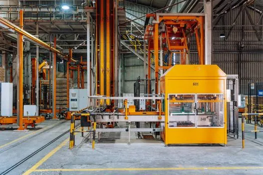
A 90° tilt does not guarantee that a gravity casting cell can handle a selected die and casting. The FILL machine has a clamping surface of 1,300 mm long by 900 mm deep, a 900 mm minimum opening width, a 1,100 mm maximum opening width, and a maximum tool weight of 3,000 kg [S1].
An automatic gravity die casting cell based on the tilting SA-Foundry ALG-1500*1300 machine is shown in the source, but the supplied excerpt does not provide its plate, die, force, or hydraulic-pressure specifications [S5]. These values show why angle, platen size, force, and tooling mass must be evaluated together rather than treating tilt range as a stand-alone machine rating.
Applications, limits, and process failure modes
Tilting gravity equipment is suited to gravity, tilt-pour, and reverse-tilt permanent-mold casting, including dies with metal or sand cores [S1][S5]. A documented production operation uses two tilt-pour machines for roughly 300–500 pieces per year and volumes extending to 50,000 pieces per year, while thicker-wall parts suitable for gravity filling run at about 50 pieces per hour [S3].
Static pouring into a fixed upright die is the main process alternative, but it creates more turbulence than tilt pouring [S3]. Low-pressure die casting is a different fill method because metal rises from below under low pressure, while high-pressure die casting uses high-pressure injection and different tooling [S3]. For a controlled-fill comparison, consult the entries for gravity die casting die and low-pressure die casting machine rather than treating these processes as interchangeable.
The main failure modes are oxide entrapment, splash during basin charging, gas porosity, incomplete cavity fill, turbulence, and gating complexity [S2][S3][S5]. Reverse tilt can remove some runner requirements, but direct pouring and eliminated runners remain design-dependent rather than universal claims [S2].
Program the fill, then validate it
The defensible choice is a machine with at least the angle required by the die orientation: 90° for conventional upward filling, 120° where reverse-tilt geometry requires it, or a bidirectional range when the cycle must move through negative and positive angles [S1][S6].
Validate the sequence on the actual die: preheat and coat the mold, close it with cores installed, charge a measured quantity of metal into the basin near horizontal, tilt at a programmed rate, hold for solidification, then open and eject [S3]. The TILTCASTER S permits a freely definable solidification dwell and direct pouring during tilting, but that capability does not replace process validation [S1].
Two trackable signals should close the setup review: confirm that the programmed angular path covers the required fill geometry, and compare the achieved fill against the machine's published tilt-speed range of 0.06–30°/s for servo-controlled equipment [S1]. The die design, gating route, and programmed angle must agree before a production cell is accepted.