
Shops running tight-tolerance aerospace or mold work should spec a shop-floor coordinate measuring machine with at least 0.005 mm (5 µm) repeatability, 0.5 µm/mm accuracy class, and active vibration control before considering any brand, per Industrial Monitor Direct's 2026 metrology-lab selection guide [S2].
Manual granite-plate, height-gage, and dial-indicator stacks stay viable down to 0.01–0.05 mm accuracy on simple prismatic parts, but break-even on CMM ownership arrives around 80 outsourced measurements per year, once contract CMM inspection runs €700–1,000 per part [S2]. A shop-floor-rated machine such as the Mitutoyo MiSTAR 555 is documented as a CNC CMM built for outside-the-measuring-room duty, with environmental hardening as a published design axis [S3][S5].
Start with the GD&T budget, not the spec sheet
Pull the tightest part tolerance on the shop floor first; for composite-mold work the reference budget is typically ±0.01–0.05 mm flatness, 0.05–0.10 mm perpendicularity and parallelism callouts, and hole/pocket dimensional checks at the same order [S2]. If the tightest callout sits below 0.01 mm, manual calipers and height gages drop out and a contour measuring machine with triggering probes becomes the only credible tool. A typical CMM datum reference frame (DRF) of three mutually orthogonal planes (often A-B-C) plus a probe qualification sphere defines the coordinate system every downstream GD&T datum is evaluated against. Surface finish Ra 0.8 µm and tighter also forces a filtered probe strategy: either an analog scanning head, a ruby-stylus star probe, or a vision-on-CMM hybrid to avoid styli skating across peaks.
For freeform 2D profiles on turned or stamped parts, a vision measuring machine or optical comparator handles the geometry at 0.001 mm scale resolution, but cannot certify 3D perpendicularity or flatness on a Z-axis plane [S2]. If the workload mixes 2D profile and 3D GD&T, a vision measuring machine covers the former and a shop-floor CMM covers the latter; bolting both into one metrology cell is now a common aerospace pattern.
Shop-floor CMM vs bridge CMM vs portable arm: decision table
Selection between fixed bridge, shop-floor (moving-bridge on granite or steel base), and portable articulated-arm systems depends on part envelope, accuracy demand, and ambient class, per a 2026 Dataintelo portable CMM market brief [S6]. The table below compresses the criteria for a metrology cell sized to small-to-medium prismatic and turned aerospace parts:
Selection between fixed bridge, shop-floor (moving-bridge on granite or steel base), and portable articulated-arm systems depends on part envelope, accuracy demand, and ambient class, per a 2026 Dataintelo portable CMM market brief [S6]. The table below compresses the criteria for a metrology cell sized to small-to-medium prismatic and turned aerospace parts:
<strong>Shop-floor CMM</strong> (Mitutoyo MiSTAR 555 class): 0.005 mm repeatability, 0.5 µm/mm accuracy grade, working envelope typically 500–700 × 700–1000 × 400–500 mm, active vibration isolation, thermal class 18–22 °C ±1 K, IP-rated covers, robotic load/unload ready. Best fit: 0.01–0.05 mm tolerance, 24/7 cell integration, medium envelope.
<strong>Fixed bridge CMM (climate room)</strong>: 0.002 mm (2 µm) precision grade repeatability, larger envelope to 1000+ mm, requires 20 ±0.5 °C lab, 2,000+ kg foundation, no vibration. Best fit: sub-0.01 mm GD&T, metrology lab central inspection, reference-master work.
<strong>Portable articulated arm</strong>: 0.03–0.05 mm volumetric accuracy over 1.5–3.0 m reach, no fixed installation, handheld or tripod mount, no environmental class. Best fit: large fabricated structures, in-machine inspection, field service where the part cannot move.
<strong>Optical comparator / vision system</strong>: 0.001 mm scale resolution, 2D profile only, low cost, no 3D GD&T. Best fit: turned threads, gaging, first-article go/no-go.
Quoting the selection rationale directly: "The selection between portable and fixed CMM technologies depends on production requirements, available facility space, measurement accuracy demands, and..." [S6]. The same four-axis matrix is exactly the buying checklist for a shop-floor metrology cell.
Why the metrology cell is not a measuring room anymore
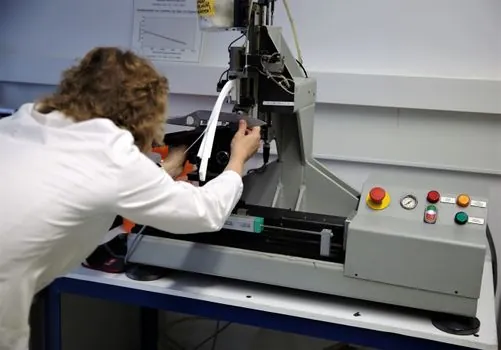
Shop-floor-rated CMMs such as the MiSTAR 555 are explicitly marketed as "highly environment-resistant Coordinate Measuring Machines" that "allow shop-floor inspection outside the measuring room" [S3][S5]. The engineering reality behind that claim is a sealed linear-encoder scale system (typically 0.1 µm resolution), air-bearing or rigid-roller guides with thermal compensation, and a controller that applies part-temperature compensation against a shop-traceable standard.
In the Acutec Precision Aerospace deployment, a shop-floor CMM was paired with a Fanuc-robotic mill-turn cell to deliver lights-out throughput "without compromising a micron of quality" [S4][S5]. The integration lessons that hold for most cells: (1) standardize the part datum scheme (3-2-1 locating principle on the fixture plate), (2) keep the probe change rack within the cell envelope to avoid robot reach issues, (3) program the inspection cycle in the same CAM environment as the cutting cycle so the same tool offsets feed both machining and inspection loops, and (4) thermal soak the part 30 min before the first touch if the cell sees doors opening across day/night shifts.
Calibration, traceability, and the standards you should actually cite
Every CMM in a metrology cell should ship with a traceable calibration certificate per ISO 10360-2 (length-measurement accuracy) and ISO 10360-5 (probing-error), and a daily check against a calibrated sphere or ring gage before the first part. For sub-0.01 mm work, a dimensional metrology program should also include a quarterly ball-bar test (circularity, typically 50–150 mm radius) and an annual replacement of the probe-qualification reference sphere. [S2]
Two harder constraints are easy to miss. First, granite base flatness: a 0.01 mm/m grade on a 700 mm base still allows 7 µm of sag across the table, which directly eats your Z budget. Second, controller-side thermal compensation: a 1 °C shop swing on a 1 m aluminum column adds ~23 µm of length change, larger than the probe's own repeatability. Specify the cell's allowed ambient band (18–22 °C ±1 K is a common spec) and reject bids that only quote a bare machine thermal coefficient without a controller model.
Who should NOT buy a shop-floor CMM
Three workloads do not justify a shop-floor CMM in 2026: (1) job shops running loose 0.05–0.10 mm tolerances on a handful of parts a week, where digital calipers, height gages, and a granite plate cover the budget [S2]; (2) high-volume turned-part runs where an in-process post-process gage on the lathe or a vision measuring machine inline delivers faster cycle time; (3) very large fabricated weldments where a portable arm or laser tracker at 0.03–0.05 mm volumetric accuracy is the only practical tool, since no bridge CMM fits a 5 m hull plate [S6].
For the central case (a 50–200 part per week mix of aerospace prismatic and small freeform geometry, 0.01–0.05 mm tolerance, 500–800 mm envelope), a shop-floor CMM with 0.005 mm repeatability is the right anchor, and the 80-measurement annual breakeven rule from the 2026 reference guide is the cleanest go/no-go gate [S2]. For adjacent process cells that need force feedback on a clamp torque to avoid distortion, see this torque wrench tester vs force gauge corrosion-resistance decision map; for environmental stress screening of fixtures and datum blocks, the environmental test chamber duty-standard-envelope guide is the parallel reference.
Trackable next signals: (1) Mitutoyo's MiSTAR-series firmware revision notes and (2) any ISO 10360-2/-5 revision drafts in the ISO TC 213 work program, both of which will reset published accuracy claims during the 2026–2027 window.