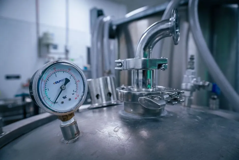
On a shop air or instrument air header running 7-10 bar, the practical sizing rule is to pick a transmitter whose upper range value (URV) is roughly 1.5x the highest expected pressure including spikes, so a line peaking at 10 bar takes a 0-16 bar unit rather than a 0-25 or 0-40 bar unit that would force the normal operating point into the noisy lower fifth of the span [S3].
Compressed air duty is a low-pressure, clean, dry gas service, so the same pressure transmitter families used for general process lines apply, with two discipline points that bite first: keep the URV close to the working point, and confirm the control system's analog input card before the unit is wired [S3][S4].
Range and span: the 1.5x rule of thumb
The most common field error is oversizing for safety: a 0-50 bar transmitter on a process that sits at 8-12 bar is operating in the bottom fifth of its span, where the same percentage-of-full-scale error resolves to a much larger real-world deviation, and a 0-100 bar unit on the same duty gives up even more usable resolution [S3]. A widely used sizing heuristic sets the URV at roughly 1.5x the expected maximum including transients, so a process that runs at 20 bar with occasional 28 bar spikes takes a 0-40 bar device; that gives headroom for surge while keeping the normal operating point near mid-span, where linearity and thermal stability are best [S3].
For typical shop air, the three numbers to record before any order are minimum operating pressure (often near 0 bar during off-load cycles), normal operating pressure (the regulator setpoint, usually 6-8 bar), and maximum including spikes (compressor cut-out plus any water-hammer or receiver recharging transient). A 0-10 bar unit covers most 7 bar shop air, a 0-16 bar unit covers 10 bar systems with margin, and a 0-25 bar unit is the practical ceiling for most plant air at 13-16 bar [S3]. Reference spans from one widely stocked industrial line run from -1 to 12 bar up to -1 to 50 bar in the same body, so the same housing can be used across a plant with mixed pressure tiers [S3].
Output signal: 4-20 mA, 0-10 V, or HART
Three outputs dominate the spec sheet: 4-20 mA current loop, which is the industrial default because it is noise-resistant over long cable runs, easy to wire into any PLC or DCS analog input, and self-diagnosing in a basic sense (a reading of 0 mA points to a wiring fault, not a real zero) [S3]. 0-10 V or 1-5 V voltage outputs are common in HVAC and building automation with shorter cable runs and are less tolerant of electrical noise than current loops but simpler when the controller card is voltage-based [S3]. Digital or fieldbus output (HART, Modbus) is used where the transmitter has to talk directly to a network rather than a single analog channel, typically in larger or more heavily instrumented systems [S3][S4].
The single most common return reason is output mismatch: the transmitter is correct, but the receiving analog input card is not. Confirm the card type before ordering [S3]. For most compressed air headers a 4-20 mA + HART device covers the standard control loop while still allowing handheld configuration and remote diagnostics, so it is the default for new plant air installations; pure 0-10 V is reserved for short cable runs to a dedicated controller, and FOUNDATION Fieldbus or PROFIBUS PA appear only on larger sites that have standardised on a digital backbone [S3][S4].
Process connection and wetted materials
For shop air and instrument air the standard process connection is 1/4 in NPT male or G1/2 male, with 1/2 in NPT common on larger header taps; the wetted path should be stainless 316L with a fluorocarbon (FKM) or, for higher temperature dryer exhaust, FFKM seal, which keeps the moisture-laden air from corroding the diaphragm and the process port over years of duty [S4]. A dry gas service allows the use of a standard thin-film or piezoresistive cell with a welded stainless isolator, and for most compressed air applications there is no need for exotic alloys.
Two failure modes are specific to compressed air. First, the high humidity at the compressor discharge condenses inside the impulse line and the sensor cavity if no dryer is upstream, so any tap downstream of an aftercooler or refrigerated dryer should be fitted with a siphon loop and, ideally, a small inline particulate filter to keep water and rust from reaching the diaphragm. Second, pulsation from a reciprocating compressor can drive a fast transmitter into over-range at every stroke, so a snubber or a 1-2 m length of small-bore tubing between the tap and the transmitter body is the standard mitigation. Both modes are well known in instrument air practice and are caught at the piping stage, not by buying a more expensive transmitter [S2][S3].
Static pressure, line pressure, and where a dP cell makes sense
A gauge pressure transmitter measures the working pressure of the line against atmosphere; a differential pressure transmitter measures the difference between two taps and is the right tool for filter condition monitoring, receiver level-by-pressure, and the increasingly common differential pressure across a desiccant tower in a compressed air dryer [S2]. A typical dP cell on a coalescing filter sees a clean baseline of 0.1-0.3 bar and a change-out trigger near 0.7-1.0 bar, well within the 0-1.6 or 0-2.5 bar URV that is a common industrial size for that duty [S2].
For differential flow measurement, the same dP cell is paired with an orifice plate or pitot tube and the static line pressure of the air can be 7-10 bar, while the differential the cell has to resolve is often a few millibar to a few tens of millibar; that is a 100:1 or 1000:1 turndown and is exactly the working regime where the cell's static pressure rating and the calibration of the differential channel both matter [S2]. When the duty is to track the differential across a filter or a dryer tower, not to compute flow, a standard dP cell with a 0-1.6 bar or 0-2.5 bar span and a 4-20 mA output is usually the correct call; for custody-style accuracy on metered compressed air, a higher static-rated cell with a smaller calibrated span is needed [S2]. Differential pressure devices accounted for about 51.24% of pressure transmitter market revenue in 2023, reflecting how often the dP cell is the workhorse of filtration, level, and flow monitoring in plant air and process gas service [S2].
Air quality side: pairing the pressure transmitter with dew point and quality sensors

Pressure on its own does not tell you whether the air is dry enough for the downstream pneumatic instruments, so a modern compressed air audit pairs a pressure transmitter on the header with a dew point transmitter downstream of the dryer and a flow meter on the branch [S5][S6]. A pressure transmitter is the right call for static pipeline pressure and tank pressure, while for atmospheric or absolute reference duties (for example, a barometric correction on a flow computer) the absolute variant is the correct device, and a gauge variant is the wrong one because it adds atmospheric variability to the reading [S4].
Dew point measurement is the practical check on dryer performance: refrigerated dryers typically deliver +3 deg C pressure dew point, desiccant dryers -40 deg C or lower, and the dew point transmitter sits on a branch line after the dryer with its own sample conditioning so that condensate and particulates do not poison the sensor [S6]. Real-time compressed air monitoring combines pressure, dew point, and flow on a single dashboard so that the team can trigger alerts when thresholds are crossed, and the data also feeds energy audits because pressure drop and leakage both show up as deviation from the expected pressure profile on the header [S5]. For a facility auditing a compressed air system in 2026, the minimum instrument package is a gauge pressure transmitter per main header, a dP cell across each coalescing filter, a dew point transmitter downstream of each dryer, and a flow meter per major branch; the pressure transmitter by itself covers only part of the duty [S5][S6].
Selection checklist for a 2026 plant air install
The four calls to make before ordering, in order: range, output, process connection, and wetted material. Range: URV at 1.5x maximum including spikes, normal operating point at 30-70% of URV; for 7 bar shop air that is a 0-10 bar or 0-16 bar gauge transmitter [S3]. Output: 4-20 mA + HART for most PLC/DCS, 0-10 V only for short cable runs to a known voltage-input card [S3][S4]. Process connection: 1/4 in NPT or G1/2 male on the header tap, with a siphon or snubber between the tap and the transmitter body to keep condensation and pulsation off the diaphragm [S2][S3]. Wetted material: 316L stainless body and diaphragm, FKM seal for standard air, FFKM if the location is downstream of a high-temperature desiccant regen line [S4].
Skip the mainstream 4-20 mA gauge transmitter only if the duty is actually absolute (barometric correction, vacuum reference) in which case an absolute cell is needed, or if the measurement is filter delta or dryer bed delta in which case a dP cell is the correct device, not a gauge cell with one port plugged. For a comparison framework, gauge vs absolute vs differential cells line up on three criteria that matter in plant air: reference (atmospheric, vacuum, two-port), typical URV on a 7-10 bar system (0-10 bar gauge, 0-1.6 bar absolute, 0-1.6 bar dP), and main application (header pressure, barometric correction, filter and dryer condition). A general guide to working with dP cells in process service is laid out in this differential pressure transmitter practical primer, and the chemistry skid side of pressure sensing is covered in pressure sensor selection for chemical dosing skids; the two together cover roughly the range of duties a single plant will see across its air, water, and chemical lines.