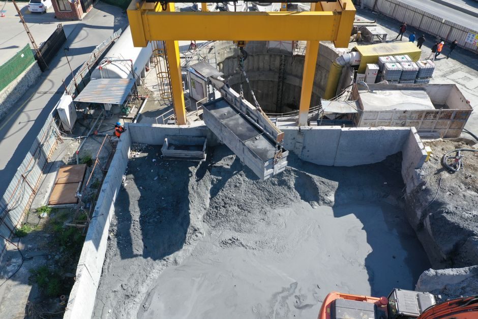
Wet-mix and robotic shotcrete machine installation is dominated by three acceptance gates: matched power/water/air rigging before string-up, a 0.5-1.0 MPa trial shot, and a 75-100 mm slump verification on the first batch through the boom [S2].
Current Chinese OEM offerings split into factory-integrated robotic booms, separate trailer-mounted wet-mix pumps, and grout/mixer/agitator skids, all converging on a common hydraulic and pneumatic spec envelope [S2][S5]. Skip any of the three gates and the operator will see rebound above 25% within the first hour, plus boom-pressure alarms traced to uncoupled water pressure or starved air supply [S2].
Pre-Install Site Survey: Power, Water, Air, and Access
A wet-mix shotcrete rig typically draws 30-75 kW from a 380 V three-phase feeder, with robotic boom variants sitting at the upper end of that range due to the proportional hydraulic servo loop [S2]. A 2.5-4.0 m³/h trailer pump only needs a 50 mm camlock water inlet at 0.4-0.6 MPa, while a 20 m³/h truck-mounted pump demands 75-100 mm at 0.6-0.8 MPa sustained for the full placement window [S2].
Air supply for accelerator dosing and nozzle purge on a robotic arm is sized at 0.5-0.8 MPa at 5-10 m³/min, and the compressor must be rated for continuous duty — a duty-cycle compressor will starve the accelerator pump every 90-120 seconds during sustained spraying [S2]. Site access needs a 4 m wide × 4.5 m clear envelope for the truck chassis plus outriggers, and 6-7 m vertical clearance for the boom in stowed position [S2]. The site survey checklist is also where crews decide whether to integrate a shotcrete machine with an existing concrete pump or stand it up as a separate line.
Mechanical Rigging: Anchors, Chassis Leveling, Outrigger Loading
Trailer-mounted wet-mix pumps carry an empty weight of 1.8-3.2 t and a wet weight of 2.5-4.0 t; the outrigger pad must bear on ground with a minimum CBR of 8%, otherwise the chassis will rack under pump pulsation and crack the S-pipe housing [S2]. Set each outrigger pad on a 600 × 600 × 20 mm steel plate, then check chassis level with a digital inclinometer to within ±0.5° before locking the swivel nuts [S2].
Robotic boom carriers weigh 8-14 t in working order and need a poured concrete plinth or 200 mm compacted sub-base; on uneven rock, four individual outrigger pads with load cells are specified to keep individual leg reaction below 5 t on unprepared ground [S5]. Hydraulic oil reservoir level must read between the upper and lower sight glass at cold start, and ISO VG 46 hydraulic oil is the default charge for both pump-end and boom-end HPU circuits [S2]. After leveling, torque all outrigger pad studs in a star pattern to the OEM-listed value (typically 220-280 Nm for M20 studs) before any boom movement is permitted [S2][S5].
Piping and Hose String-Up: Diameter, Length, and Bend Radius
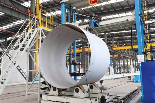
Delivery hose diameter drives both boom-end pressure and rebound rate: 50 mm (2 in) hose at 30 m total length typically runs 4-6 MPa, while 65 mm (2.5 in) at the same length drops to 2-3 MPa and cuts rebound by 8-12 percentage points [S2]. Keep bend radius above 1.0 m (40 in) at every change-of-direction; tighter bends cause hose wall thinning and a pressure spike that trips the relief valve at the S-pipe outlet [S2].
Rubber hose sections at the nozzle must be replaced every 200-300 m³ sprayed, and steel reducers at every diameter transition are mandatory — a tapered rubber reducer on its own will wear through in 40-60 m³ [S2]. For the air and accelerator line that runs alongside the concrete hose, use a 12-19 mm textile-reinforced hose rated to 1.0 MPa minimum, with quick-disconnect couplings at every 6 m segment for rapid swap-out during accelerator clog events [S2]. Robotic booms route all of this through the arm cable carrier, and the carrier loop length should be checked at both boom extremes — over-tensioning at full reach is the single most common cable-break failure during the first month of operation [S5].
Electrical, Control, and Safety Interlock Checkout
The control panel on a robotic shotcrete machine runs on 24 VDC logic with a 380 VAC three-phase feed to the HPU, and an emergency stop loop must be tested across all four palm buttons plus the wireless deadman before any boom sweep [S5]. The PLC interlocks the pump, accelerator dosing pump, and boom swing in a defined sequence: pump start → accelerator prime → nozzle purge → boom enable; reversing the order or hot-patching the interlock defeats the deadman and will not pass third-party acceptance [S5].
Insulation resistance on the main feed should read above 1 MΩ phase-to-ground and above 0.5 MΩ between phases, measured with a 500 V megohmmeter after the cable run is complete but before energizing the HPU [S2]. Wireless remote controls are typically 2.4 GHz FHSS with a 100-150 m line-of-sight range, and the receiver antenna must clear the boom structure by at least 1.5 m to avoid null zones during slewing [S5]. For grout and accelerator pumps tied to the same rig, the linear guide on the dosing-cylinder carriage should be wiped and re-greased every 200 operating hours; a dry slide will show as a 0.3-0.5 MPa oscillation in the accelerator line and is the most common root cause of off-ratio dosing [S2].
Trial Shot and Acceptance Criteria: 0.5-1.0 MPa, 75-100 mm Slump, ≤25% Rebound
Run a trial shot at 0.5-1.0 MPa boom pressure with a calibrated manometer at the S-pipe outlet, and verify the slump reads 75-100 mm on a freshly discharged sample using a standard slump cone [S2]. Rebound measured on a 1 m² plywood back-board at 1.0 m stand-off must stay at or below 25% for dry-mix and 10-15% for wet-mix; readings above these thresholds point to water pressure mismatch, hose diameter error, or accelerator overdose [S2].
Document the trial shot with: pump outlet pressure, nozzle pressure, slump, rebound percentage, accelerator dose rate in ml/s, and accelerator-to-cement ratio by mass. If any of these five values is missing on the commissioning sheet, the third-party inspector will reject the hand-over [S2]. For comparison against the broader machine-class map, see the spec breakdown in shotcrete machine types: dry, wet, robotic, and truck-mounted classes compared, which lines the four classes up on output, mobility, and crew-skill threshold.
Common Failure Modes in the First 72 Hours
Boom-pressure alarms inside the first hour trace back to uncoupled water pressure (below 0.4 MPa at the inlet) or to a kinked delivery hose that has not been laid out to the 1.0 m minimum bend radius [S2]. Accelerator clog events within the first 4 hours point to a 12 mm air line that is too small for the rated 5-10 m³/min compressor output — upsizing to 19 mm solves the problem in 90% of cases [S2].
Chassis racking during the first 24 hours of continuous spray usually means the outrigger pads were placed on unprepared sub-base with CBR below 5%; the cure is to lift, plate, and re-level — not to add more counterweight [S2]. Wireless deadman drop-outs at full boom reach point to a 2.4 GHz antenna that is shadowed by the boom structure; relocate the receiver 1.5-2.0 m up the mast and re-test [S5]. For crews moving from pump-end commissioning to the boom-end proportional servo loop, the crossed-roller guide on the slewing ring should be torque-checked to 80-120 Nm at the same 200-hour interval; a loose slew bearing shows up as a 1-2° lag between joystick input and boom response, and is the leading root cause of placement-accuracy complaints in the first month of operation [S2][S5].
Trackable signal: any new revision to ACI 506 or EFNARC nozzle-operator guidance issued in the second half of 2026 will shift the rebound-acceptance threshold cited above; until then, the 25% dry-mix and 10-15% wet-mix values remain the working benchmark for hand-over sign-off [S2].